CAD Models & Simulations Gallery
Discover a curated collection of high-fidelity CAD models, showcasing rocket engines, turbopumps, aerospace flow instrumentation, and re-entry vehicles. Each model is supported by detailed engineering analysis, including CFD simulations of shockwaves, hypersonic flow around re-entry bodies, and thermal and structural evaluations under extreme operating conditions. From shock wave visualization in high-Mach atmospheric re-entry to turbopump flow dynamics and thrust chamber cooling, every project features 3D visualizations, performance plots, and technical documentation—highlighting real-world design intent and functional behavior.
← Select a model from the sidebar to begin
Rocket Engine Turbopump
A detailed model of a rocket engine turbopump assembly. This critical component is responsible for delivering propellants at high pressure and flow rates to the combustion chamber. The design features both turbine and pump sections with precision-engineered impellers and housing.
Technical Analysis
Design Features
-
The turbopump assembly is designed with a strategic choice of materials to balance
structural performance, chemical compatibility, and mass efficiency. The volute casing is
6061-T6 aluminum alloy
fabricated from , selected for its lightweight properties, good
corrosion resistance, and ease of machining—ideal for non-rotating, non-direct-contact
regions where reducing system mass is critical.
In contrast, the inducer, impeller, and stator vanes are made from Ti-6Al-4V titanium alloy,
owing to its high specific strength, excellent fatigue resistance, and compatibility with
cryogenic oxidizers such as liquid oxygen. Titanium also offers superior erosion resistance
in high-speed rotating components and maintains mechanical integrity under extreme pressure
and thermal gradients. This material configuration ensures a robust and efficient turbopump
capable of operating reliably under demanding rocket propulsion conditions.
- Staging: Multi-stage centrifugal pump, with first stage inducer and second stage impeller
- Fluid: RP-1
- Mass flow rate: 100kg/s
- Speed: 35,000 RPM
- Pressure difference: 175 bar
- Specific speed: 38.3
- Specific work: 21,472 m^2/s^2
- Power input: 2147.2 kW
- Head: 2189.6 m
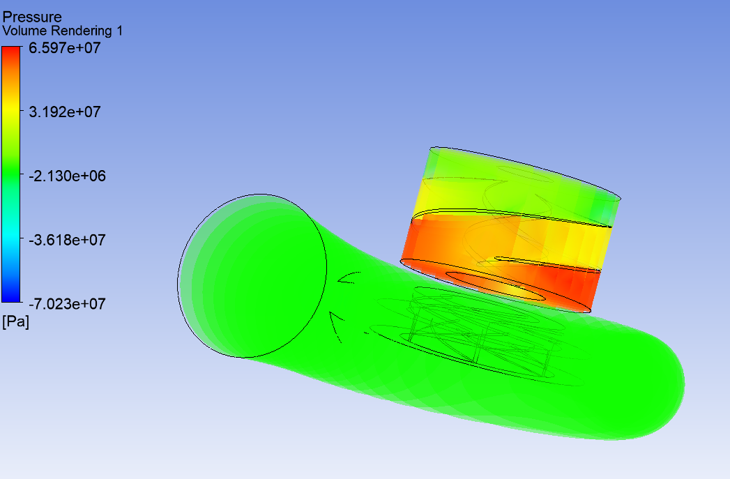
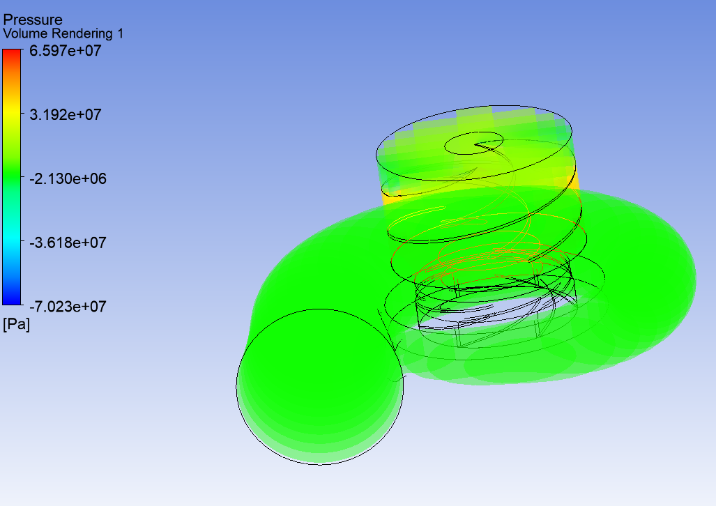
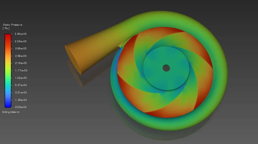
Inudstry Standard Water Pump
A detailed model of a rocket engine turbopump assembly. This critical component is responsible for delivering propellants at high pressure and flow rates to the combustion chamber. The design features both turbine and pump sections with precision-engineered impellers and housing.
Technical Analysis
Design Features
-
The pump assembly is designed with a strategic choice of materials to balance structural
performance, chemical compatibility, and mass efficiency. The volute casing is 6061-T6 aluminum
alloy, selected for its lightweight properties, good corrosion resistance, and ease of
machining—ideal for non-rotating components where reducing system mass is critical. In contrast,
the rotor (impeller) is made from stainless
steel, owing to its high strength,
excellent corrosion and erosion resistance in water service, and ability to maintain mechanical
integrity under high flow rates and pressure differentials. This material configuration ensures
a robust and efficient single-stage centrifugal water pump capable of reliable operation in
demanding industrial conditions.
- Fluid: Water
- Mass flow rate: 10kg/s
- Speed: 2900 RPM
- Pressure difference: 2.5 bar
- Specific speed: 25.5
- Power input: 2.505 kW = 3.13HP
Multi Stage Compressor
A detailed model of a 3 stage compressor.
Design Features
- Staging: 3 Stage
- Working fluid: Air
- Mass flow rate: 20kg/s
- Speed: 32,000 RPM
- Pressure difference: 15 bar
- Specific speed: 51.2
- Power input: 6880 kW
Turbine for gas generator of a Liquid Rocket Engine
Design Features
- Staging: Single Stage
- Working Fluid: Combustion products of RP-1 and LOX
- Mass flow rate: 8kg/s
- Speed: 36,000 RPM
- Pressure ratio: 10
- Power input: 4.2MW
Technical Analysis
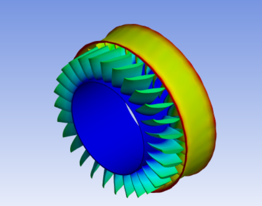
This turbine is the energy-extraction stage of a gas-generator cycle used in liquid-propellant
rocket engines. It converts thermal and pressure energy from hot gas produced in the gas
generator
into rotational mechanical power to drive two separate turbopumps — one for fuel and one for
oxidizer. As such, the turbine is a central, safety-critical subsystem whose performance and
reliability directly determine engine thrust control, propellant feed stability, and overall
mission
success.
Key functional elements and design considerations:
• Working principle and flow path. Hot,
high-enthalpy gas from the gas generator is expanded through
the turbine nozzle and impinges on the turbine rotor blades (stages). The gas does work on the
rotor, producing torque transmitted via a high-precision shaft and gearing (or separate shafts)
to
the fuel and oxidizer pumps. The exhaust is routed to an appropriate dump or recombination path
per
engine architecture.
• Dual-pump drive architecture. The turbine
is
configured to split delivered power between two
turbopumps. This may be accomplished with a single rotor and gearbox that drives two shafts, or
with
a coaxial/multi-spindle arrangement. Power split, phasing, and torsional dynamics are engineered
so
both turbopumps receive stable torque across the operating envelope while avoiding resonant
shaft
modes.
• Thermodynamic performance. Key
performance
metrics include turbine inlet temperature and pressure,
mass flow rate of the gas-generator exhaust, stage efficiency, isentropic work output, and
rotational speed. The turbine design is optimized to deliver the required shaft power at the
most
efficient tradeoff between stage loading and blade Mach/turning limits, while maintaining
acceptable
turbine entry temperature margins.
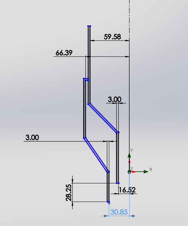
• Aerothermodynamics and blade design.
Rotor
and stator blade geometries are designed using 2D/3D
aerodynamic analysis (mean-line design and throughflow methods) and validated with CFD to manage
loading, shock formation (if transonic), secondary flows, and loss mechanisms. Multi-stage
designs
balance stage loading and blade height to keep tip speeds, stresses, and Reynolds-number effects
within allowable ranges.
• Materials and high-temperature
protection.
Turbine components facing hot gas are manufactured from
nickel-based superalloys or other high-temperature alloys selected for creep, fatigue, and
oxidation
resistance. Thermal barrier coatings (TBCs), diffusion barriers, and selective alloying are used
as
needed. For the hottest regions, active cooling (film or internal convection cooling channels)
may
be employed to protect blades and vanes.
• Bearings and seals. Rotor support uses
high-precision bearings — typically a combination of
hydrodynamic journal bearings for steady-state support and angular-contact or rolling bearings
for
transient loads — selected for high speed, low friction, and long life. Sealing systems
(labyrinth
seals, brush seals, or abradable seals) minimize leakages between hot gas and bearing cavities,
and
control cross-flows that could reduce efficiency or create hot-gas ingestion.
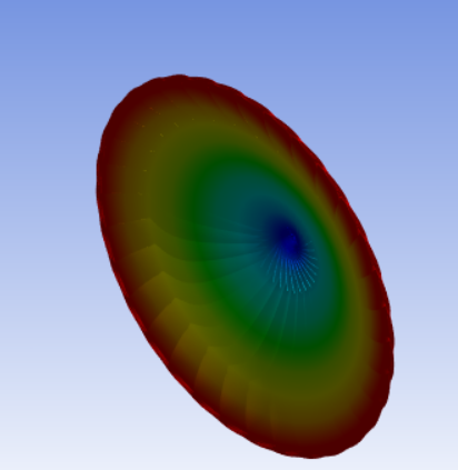
• Thermal management and structural
integrity.
The turbine housing and rotor are designed for
thermal gradients, transient startup/shutdown cycles, and rotor dynamics. Thermal expansion,
differential growth between components, and stress concentrations are analyzed with FEA. Blade
root
attachments (fir-tree, dovetail) and retention features are sized for centrifugal loads and
vibratory stresses.
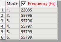
• Rotordynamics and vibration control.
Critical
speed mapping, Campbell diagrams, and modal analysis
ensure operating speeds avoid damaging resonances. Damping strategies, shaft stiffness tuning,
and
balance tolerances are applied to reduce vibration amplitudes and prevent fatigue failures.
• Gearing and power transmission. Where a
gearbox is used to supply two turbopumps at different
speeds/torques, the gearbox is designed for high efficiency and reliability, with careful
attention
to lubrication, thermal limits, backlash, and load sharing. When direct drive is used, shaft
couplings and splines are specified to handle torsional loads and misalignment.
Single Spool 5 Stage Turbine
A detailed model of a multi stage turbine that is easy to manufacture and use in a jet engine, although of old design and less efficient that dual and tri spool engines.
Design Features
- Staging: 5 Stage
- Working fluid: Air
- Mass flow rate: 900kg/s
- Inlet pressure: 42 bar
- Inlet temperature: 1173K
- Speed: 25,000 RPM
- Pressure ratio: 35
- Specific speed: 46.1
- Power input: 676.78 MW
Twin Spool Turbofan Engine
A detailed model of a twin spool turbofan engine, commonly used in commericial and military aircrafts. Comprises of fan, high and low pressure multi staged compressor and turbine.
Design Features
- Total Mass Flow Rate: 900 kg/s
- Bypass Ratio: 9
- Fan Pressure Ratio: 1.6
- Low Pressure Compressor: 5 stages. Total pressure ratio - 2
- High Pressure Compressor: 4 stages. Total pressure ratio - 13.125
- Combustion Chamber Pressure 42 bar
- High Pressure Turbine: 2 stages. Total pressure ratio - 3.7
- Low Pressure Turbine: 4 stages. Total pressure ratio - 9.456
- Fan, Low Pressure Compressor, Low Pressure Turbine Speed: 3500 RPM
- High Pressure Compressor, High Pressure Turbine Speed: 14000 RPM
- Low Pressure Compressor Power Required: 4618 kW
- High Pressure Compressor Power Required: 32249 kW
- Low Pressure Turbine Power Produced: 42848 kW
- Low Pressure Turbine Power Produced: 34015 kW
- Power avaible to auxillary systems: 40 kW
Showerhead Injector Design
A Showerhead Injector is a type of propellant injector commonly used in liquid rocket engines.
It
consists of multiple small orifices arranged in a showerhead-like pattern, typically on a flat
faceplate. Each orifice directs fuel and oxidizer into the combustion chamber, promoting
atomization
and mixing. This injector is known for its simplicity and ease of manufacturing. It is
especially
suitable for small-scale or experimental engines and is often used in educational or prototype
rocket systems.
Merits :
• Simple Design - Easy to fabricate with standard machining tools.
• Cost-Effective - Lower manufacturing and development costs.
• Uniform Distribution - Provides consistent propellant distribution across the chamber face.
• Reliable - Fewer components reduce the risk of mechanical failure.
Demerits :
• Poor Mixing Efficiency - Compared to swirl or impinging injectors, the mixing quality is
lower.
• Limited Atomization - Droplet breakup and vaporization are less efficient.
• Risk of Combustion Instabilities - May lead to uneven combustion and performance fluctuations.
• Lower Performance - Not ideal for high-performance or high-thrust applications.
Technical Specifications
- Total mass flow rate: 513.16231 kg/s
- Oxidizer mass flow rate: 440.16625 kg/s
- Fuel mass flow rate: 72.99606 kg/s
- Number of orifice for fuel flow: 500
- Diameter of each fuel orifice: 1.944 mm
- Number of orifice for oxidizer flow: 1000
- Diameter of each oxidizer orifice: 3.12 mm
Coaxial Swirl Injector Design
A coaxial swirl injector is a type of liquid rocket engine injector designed to achieve
efficient
atomization and mixing of propellants. In this configuration, one propellant (usually oxidizer)
flows through a central orifice while the other (usually fuel) is introduced tangentially
through
swirl passages, creating a hollow conical spray sheet. The high shear between the coaxial
streams
breaks the liquid film into fine droplets, promoting rapid evaporation and combustion stability.
Merits :
• Produces very fine droplets, enhancing mixing and combustion efficiency.
• Capable of stable operation across a wide range of flow rates.
• Helps reduce combustion instabilities due to uniform mixing.
• Compact design, suitable for high-performance engines.
Demerits :
• More complex to manufacture compared to simple orifice injectors.
• Swirl passages are prone to clogging or erosion under long-term operation.
• Higher pressure drop may be required to maintain effective atomization.
Technical Analysis
Ionic Thruster Mark 1
This model represents a compact ion propulsion system, designed for long-duration space missions where high efficiency and precision thrust control are essential. The thruster operates by ionizing xenon gas, accelerating the resulting ions through an electrostatic field, and expelling them to generate thrust with extremely high specific impulse (Isp).
Technical Specifications
- Electron Inlet (Discharge Cathode): The large-diameter pipe feeds electrons directly into the chamber to ionize the xenon atoms. These electrons are emitted from a cathode (typically a hollow cathode or thermionic emitter), and collide with neutral xenon atoms to generate positively charged ions (Xe⁺) through impact ionization.
- Xenon Inlet System: A series of small-diameter inlet tubes, arranged in a ring around the central chamber, introduce xenon gas uniformly into the ionization region. This ensures a stable and symmetric plasma discharge, vital for consistent thrust.
- Grid System: At the thruster's exit, a finely spaced grid structure is visible. This forms the acceleration stage, where high-voltage electrodes create an electrostatic field to accelerate positively charged xenon ions. The grid ensures beam collimation and minimizes ion divergence, improving propulsion efficiency.
- Electron Source (Neutralizer, at the end): The pipe at the end is used to inject electrons into the exhaust plume. These electrons neutralize the positive ion beam, preventing spacecraft charge buildup and maintaining electric balance in space.
Ionic Thruster Mark 2
This is a CAD model of a compact ion thruster, designed for deep space missions and low-Earth
orbit
satellite station-keeping. The design features a cylindrical discharge chamber with a central
ionization zone, enclosed between structural support plates and integrated with electrical
feedthroughs for grid or cathode connections.
Key design aspects:
Central ion emitter or cathode, potentially coupled with a gas feed (e.g., Xenon or Argon) to
generate and accelerate ions.
Mounting rods and brackets to ensure rigidity and easy CubeSat integration.
Highly reflective metallic finish, optimized for thermal resistance and space-grade durability.
This thruster aims to deliver low thrust with high specific impulse, making it ideal for
applications such as deep space navigation, constellation orbit maintenance, and attitude
control.
Future work includes plasma plume simulation, ion beam divergence analysis, and integration with
satellite power systems.
Technical Specifications
The thruster is constructed using material-specific design zones to ensure durability and performance in the harsh environment of space. Components that come into direct contact with the ionized plasma, such as the central discharge nozzle and inner acceleration surfaces, are fabricated from titanium alloy (shown in yellow-bronze color). Titanium offers excellent corrosion resistance, low sputter yield, and high thermal tolerance, making it ideal for sustained ion exposure. In contrast, the structural frame, support rods, and mounting plates are made from 6061-T6 aluminum alloy, chosen for its lightweight properties, high strength-to-weight ratio, and ease of machining—suitable for areas without direct ion impact. This strategic material segregation ensures both mission durability and mass efficiency, critical for satellite propulsion systems.
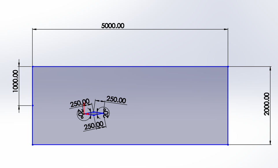
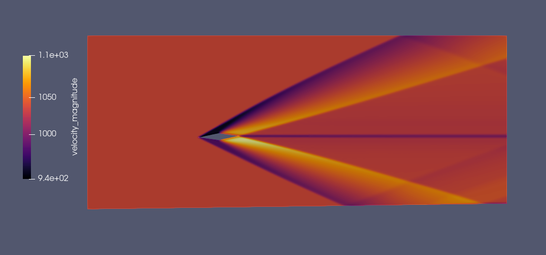
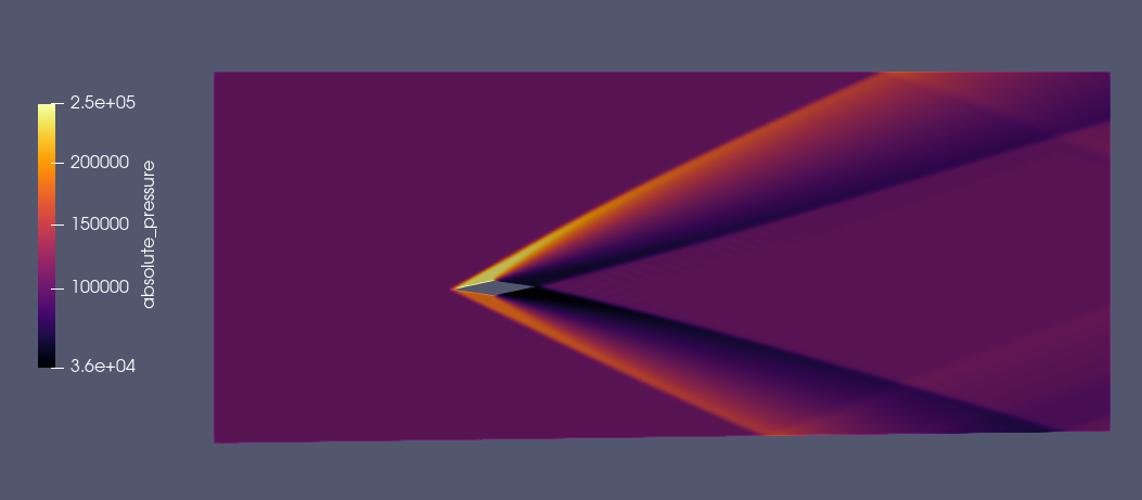
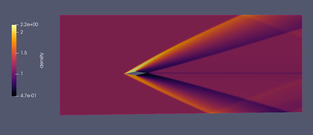
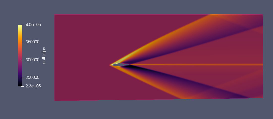
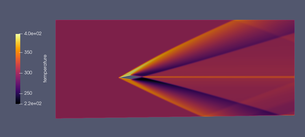
Supersonic flow over a double wedge
This project analyzes supersonic flow at Mach 3 over a double wedge geometry to study shock wave interactions and high-speed aerodynamic behavior. The sharp angles generate oblique shocks and complex shock-shock interactions, which are critical in the design of high-speed aerospace vehicles. The simulation captures pressure distribution, Mach contours, and flow separation zones, offering insights into wave dynamics relevant to supersonic and hypersonic applications.
Technical Analysis
Technical Specifications
- Boundary Conditions: Walls and pressure farfield
- Velocity: Mach 3
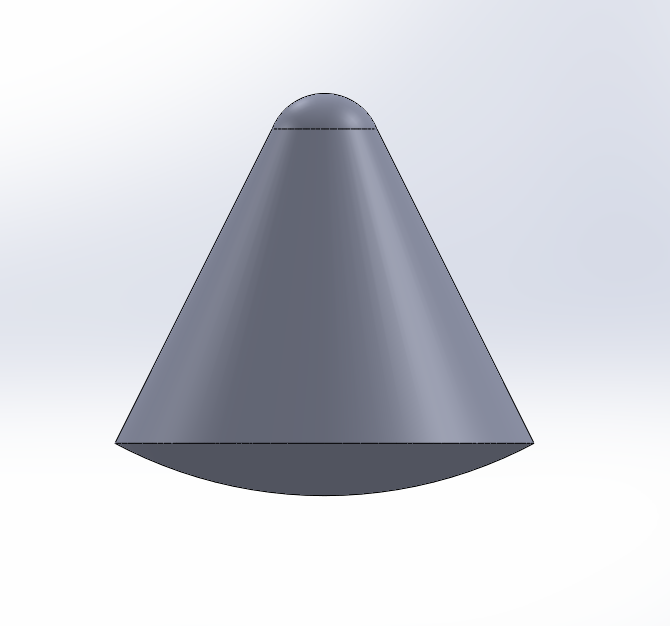
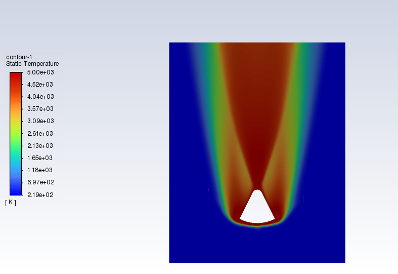
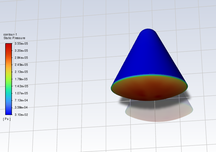
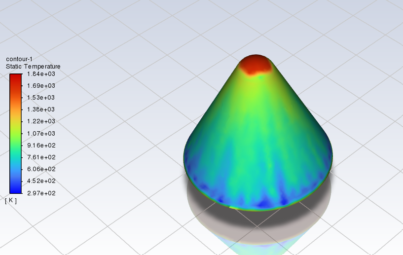
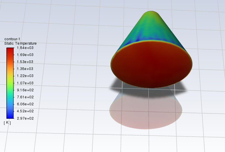
Space Vehicle Re-entry CFD Simulation
This project involves the Computational Fluid Dynamics (CFD) simulation of a space vehicle during atmospheric re-entry, conducted using ANSYS Fluent. The simulation captures critical hypersonic flow phenomena such as aerodynamic heating. The analysis focused on temperature and pressure variation around the vehicle surface. High-temperature gradients at the stagnation point and along the heat shield, essential for Thermal Protection System (TPS) design.
Technical Analysis
Technical Specifications
- Boundary Conditions: Walls and pressure farfield
- Velocity: 3D simulation run at Mach 5 and 2D at Mach 24
RS-25 Rocket Engine
A detailed 3D model of the RS-25 (Space Shuttle Main Engine), one of the most advanced rocket engines ever built. This model showcases the complex internal structure and engineering excellence of this liquid-fueled rocket engine.
Technical Analysis
Technical Specifications
- Thrust: 2,279 kN at vacuum
- Specific Impulse: 452.3 seconds (vacuum)
- Propellants: Liquid Hydrogen / Liquid Oxygen
- Chamber Pressure: 20.64 MPa
- Mixture Ratio: 6.03:1 (O2:H2)
- Total mass flow rate: 513.16231 kg/s
- Oxidizer mass flow rate: 440.16625 kg/s
- Fuel mass flow rate: 72.99606 kg/s
Chamber Performance Data
| Parameter | Injector | Nozzle Inlet | Nozzle Throat | Nozzle Exit | Unit |
|---|---|---|---|---|---|
| Pressure | 20.6400 | 20.1170 | 11.7132 | 0.0181 | MPa |
| Temperature | 3603.8962 | 3597.4647 | 3386.6714 | 1202.3447 | K |
| Enthalpy | -983.8302 | -1012.2874 | -2156.0939 | -10653.1087 | kJ/kg |
| Entropy | 17.1304 | 17.1382 | 17.1382 | 17.1382 | kJ/(kg·K) |
| Internal energy | -3177.0249 | -3201.1430 | -4198.2609 | -11358.5321 | kJ/kg |
| Specific heat (p=const) | 7.3583 | 7.3598 | 6.7559 | 2.8775 | kJ/(kg·K) |
| Specific heat (V=const) | 6.2932 | 6.2952 | 5.8003 | 2.2908 | kJ/(kg·K) |
| Gamma | 1.1693 | 1.1691 | 1.1648 | 1.2561 | - |
| Isentropic exponent | 1.1470 | 1.1470 | 1.1481 | 1.2561 | - |
| Gas constant | 0.6086 | 0.6085 | 0.6030 | 0.5867 | kJ/(kg·K) |
| Molecular weight (M) | 13.6625 | 13.6639 | 13.7885 | 14.1716 | - |
| Molecular weight (MW) | 0.01366 | 0.01366 | 0.01379 | 0.01417 | - |
| Density | 9.4109 | 9.1898 | 5.7357 | 0.0256 | kg/m³ |
| Sonic velocity | 1586.0840 | 1584.5308 | 1531.1847 | 941.3175 | m/s |
| Velocity | 0.0000 | 238.5673 | 1531.1847 | 4397.5626 | m/s |
| Mach number | 0.0000 | 0.1506 | 1.0000 | 4.6717 | - |
| Area ratio | 4.0000 | 4.0000 | 1.0000 | 78.0000 | - |
| Mass flux | 2192.3834 | 2192.3834 | 8782.3673 | 112.6356 | kg/(m²·s) |
| Mass flux (relative) | 1.0626 | 1.0904 | - | - | kg/(N·s) |
| Viscosity | 0.0001085 | 0.0001084 | 0.0001037 | 4.493e-05 | kg/(m·s) |
| Conductivity, frozen | 0.5765 | 0.5756 | 0.5425 | 0.184 | W/(m·K) |
| Specific heat (p=const), frozen | 3.786 | 3.785 | 3.75 | 2.877 | kJ/(kg·K) |
| Prandtl number, frozen | 0.7712 | 0.7124 | 0.7167 | 0.7027 | - |
| Conductivity, effective | 1.429 | 1.428 | 1.247 | 0.184 | W/(m·K) |
| Specific heat (p=const), effective | 7.358 | 7.36 | 6.756 | 2.877 | kJ/(kg·K) |
Species Composition Data
| Species | Injector mass fractions |
Injector mole fractions |
Nozzle inlet mass fractions |
Nozzle inlet mole fractions |
Nozzle throat mass fractions |
Nozzle throat mole fractions |
Nozzle exit mass fractions |
Nozzle exit mole fractions |
|---|---|---|---|---|---|---|---|---|
| H | 0.0018867 | 0.0255735 | 0.0018845 | 0.0255464 | 0.0015061 | 0.0206033 | 0.0000002 | |
| H2 | 0.0360445 | 0.2442888 | 0.0360324 | 0.2442322 | 0.0353322 | 0.2416701 | 0.0341731 | 0.2402366 |
| H2O | 0.9074897 | 0.6882250 | 0.9077116 | 0.6884641 | 0.9237487 | 0.7070161 | 0.9658269 | 0.7597632 |
| H2O2 | 0.0000430 | 0.0000176 | 0.0000430 | 0.0000173 | 0.0000212 | 0.0000086 | - | - |
| HO2 | 0.0000873 | 0.0000361 | 0.0000859 | 0.0000355 | 0.0000410 | 0.0000171 | - | - |
| O | 0.0024718 | 0.0021107 | 0.0024613 | 0.0021020 | 0.0015069 | 0.0012987 | - | - |
| O2 | 0.0053295 | 0.0022755 | 0.0053116 | 0.0022681 | 0.0034103 | 0.0014695 | - | - |
| OH | 0.0466465 | 0.0374725 | 0.0464696 | 0.0373342 | 0.0344334 | 0.0279165 | - | - |
Throttled Chamber Performance
| Throttle value | Pressure, MPa | c ef (SL), m/s | Is (SL), s | Thrust (SL), kN | c ef (opt), m/s | Is (opt), s | Thrust (opt), kN | c ef (vac), m/s | Is (vac), s | Thrust (vac), kN |
|---|---|---|---|---|---|---|---|---|---|---|
| 0.6700 | 13.79 | 3290.838 | 335.572 | 1131.453 | 4269.282 | 435.346 | 1467.860 | 4430.645 | 451.800 | 1523.340 |
| 0.7120 | 14.66 | 3329.880 | 339.553 | 1216.644 | 4272.618 | 435.686 | 1561.094 | 4433.829 | 452.125 | 1619.996 |
| 0.7540 | 15.53 | 3365.468 | 343.182 | 1302.182 | 4275.754 | 436.056 | 1654.394 | 4436.325 | 452.330 | 1716.717 |
| 0.7960 | 16.40 | 3397.900 | 346.489 | 1387.965 | 4278.518 | 436.287 | 1747.678 | 4439.458 | 452.699 | 1813.418 |
| 0.8380 | 17.28 | 3425.669 | 349.321 | 1473.141 | 4279.017 | 436.338 | 1840.107 | 4439.835 | 452.737 | 1909.263 |
| 0.8800 | 18.15 | 3451.044 | 351.990 | 1558.432 | 4279.366 | 436.386 | 1932.543 | 4440.189 | 452.773 | 2005.113 |
| 0.9220 | 19.02 | 3474.989 | 354.350 | 1644.141 | 4279.926 | 436.431 | 2024.986 | 4440.521 | 452.807 | 2100.969 |
| 0.9409 | 19.41 | 3485.175 | 355.389 | 1682.825 | 4280.117 | 436.450 | 2066.664 | 4440.665 | 452.822 | 2144.185 |
| 0.9640 | 19.89 | 3507.654 | 357.681 | 1735.196 | 4280.342 | 436.473 | 2117.436 | 4440.835 | 452.839 | 2196.830 |
| 1.0000 | 20.64 | 3541.503 | 361.133 | 1819.638 | 4280.496 | 436.508 | 2196.684 | 4441.032 | 452.865 | 2279.000 |
| 1.0260 | 20.76 | 3546.909 | 361.684 | 1831.061 | 4280.735 | 436.513 | 2209.892 | 4441.131 | 452.869 | 2292.695 |
| 1.0480 | 21.64 | 3583.027 | 365.367 | 1926.931 | 4281.107 | 436.551 | 2302.354 | 4441.412 | 452.898 | 2388.565 |
| 1.0900 | 22.51 | 3616.368 | 368.767 | 2022.804 | 4281.460 | 436.587 | 2394.821 | 4441.679 | 452.925 | 2484.439 |