One droppable housing that gives first responders power, comms, medical supplies, and survival gear where there's no road access — dropped from an aircraft and slowed enough to land intact.
The brief asked for a deployable disaster-relief package that survives an air drop and is self-sufficient once on the ground. The approach: pack everything a stranded group needs for the first 24–48 hours into one housing, size the parachute/airbag system so the drop itself doesn't destroy the payload, and run enough structural analysis to justify that the housing survives worst-case touchdown.
- 4×impact FOS (30 kN design load)
- ~6.2 m/sterminal velocity, parachute deployed
- 1.83 mmmax FEA deformation, worst case
- 4modules in one housing
Four modules, one housing
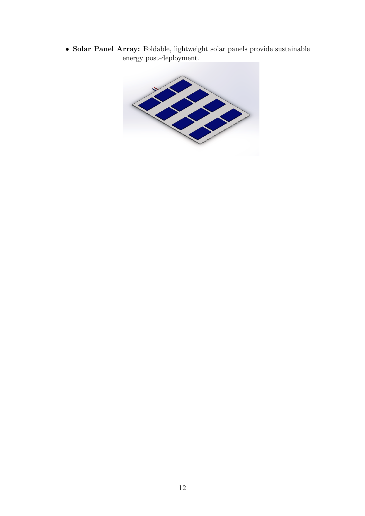
| 1 — Power & comms | LiPo pack (3,685–4,914 Wh, ~30.7 kg), Raspberry Pi 5 telemetry dashboard, ham radio + antenna, GPS, hand-crank generator, folding solar panel. ~37–49 h endurance at 100 W average. |
|---|---|
| 2 — Medical & sustenance | First-aid stock, dehydrated rations, a water purification unit (~2.76 kg dry). |
| 3 — Survival kit | Knife, rope, fire starter, flare gun, life jackets, thermal/IR camera for locating survivors. |
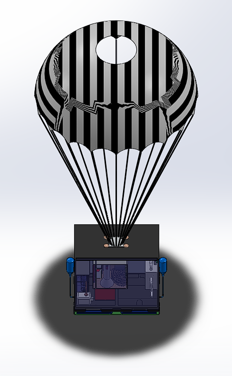
| 4 — Deployment | Parachute + CO₂-cannister airbag system, plus the final housing packaging the other three modules. |
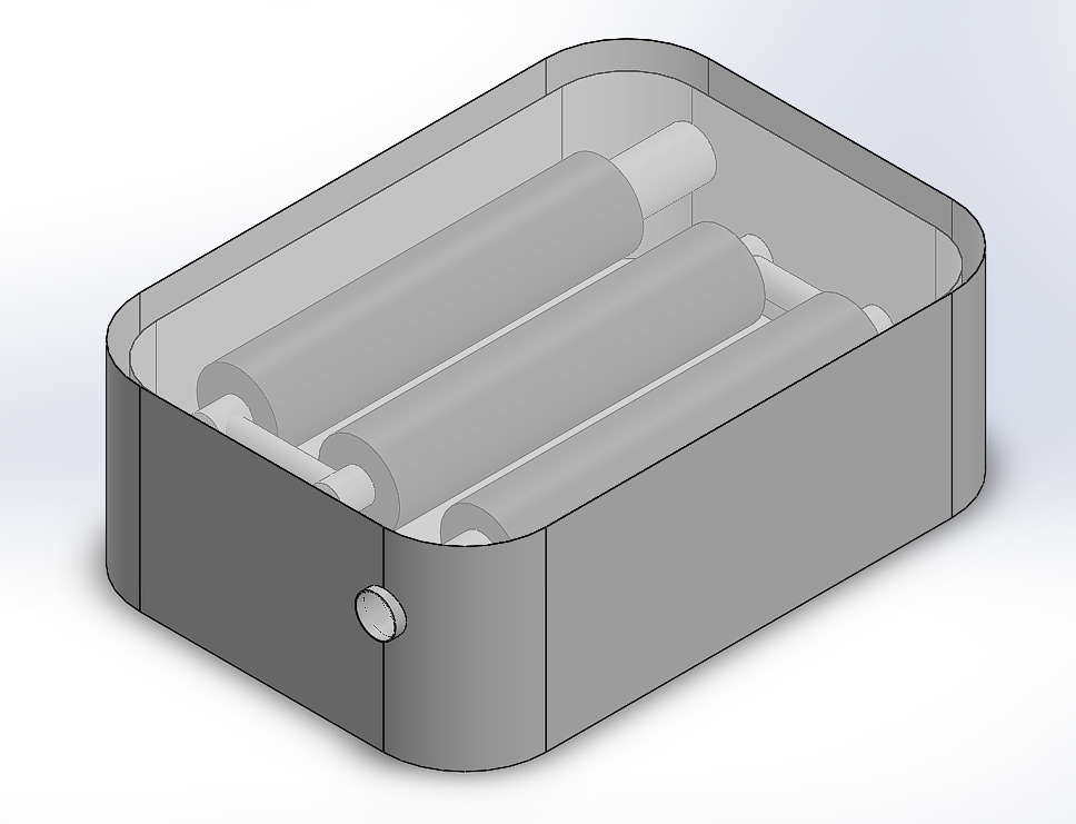
All parts are modeled as separate SolidWorks components (.SLDPRT / .SLDASM) and assembled into the final unit — ham radio box and antenna, GPS module, first-aid kit, food kit, two water-filter variants, a folding solar panel, rope, flare gun, IR camera, and the casing/airbag geometry itself.
Descent and impact
Free-fall terminal velocity (m = 75 kg, Cd = 0.6, no parachute): ~30.7 m/s. With the parachute open (effective canopy area 1.82 m², Cd = 1.75): ~6.19 m/s.
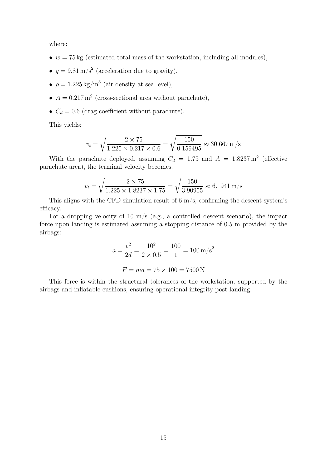
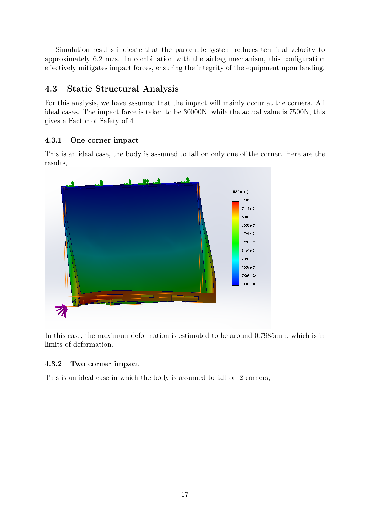
At a 10 m/s touchdown over 0.5 m of airbag stopping distance, impact force works out to 7,500 N (a = v²/2d = 100 m/s², F = ma = 75 × 100 = 7,500 N); the FEA corner-impact cases were run at a 30,000 N design load, a 4× margin.
| Corner-impact case | One corner | Two corners | All four corners |
|---|---|---|---|
| Max deformation | 0.80 mm | 1.83 mm | ~1.0 mm |
CAD-only submission — never built or drop-tested as a physical prototype. FEA cases are idealized rigid-corner strikes (no soil/water compliance), and the parachute/airbag release mechanism is CAD geometry only, with no sizing calculation behind the CO₂ inflation system.