First Principles  ·  Multi-element  ·  Web-native

INJECTOR
FORGE Design & Analysis Tool

A full-stack web application built for rocket propulsion engineers. Ten injector element families, from plain showerheads to throttling pintles, sized and analysed from first principles — no black-box CFD, no curve-fitted "looks about right" numbers. Every orifice diameter, every spray angle, every stability margin traces back to a named correlation you can look up in Sutton & Biblarz or Huzel & Huang.

Give it a thrust, a chamber pressure, an O/F ratio and a propellant pair. It gives back the hydraulics, the atomisation regime, the mixing efficiency, the combustion-stability margin, a manufacturability check, and a print-ready PDF report with the exact diagram you're looking at on screen — in under a second, so you can iterate on element count or impingement angle the way you'd iterate on a spreadsheet, except every number is physically grounded.

Showerhead Unlike / Like Doublet Triplet Quad Pentad Splash Plate Coaxial Shear Swirl-Coaxial Bi-Swirl Pintle (throttling) Gas-Gas Coaxial FFC Ring
Explore the Pipeline See the Tool
bash · injector_forge
PS> $body = @{ propellant_ox = "LOx"; propellant_fu = "LCH4"; Pc = 6000000; OF = 3.4; F_thrust = 100000 } | ConvertTo-Json
PS> Invoke-RestMethod -Uri "http://localhost:8000/api/biswirl/design" -Method POST -Body $body
# Output:
→ Stage 1: Mass Flow Allocation
  ṁ_total = 28.4 kg/s   (60 elements)
→ Stage 2: Hydraulic Sizing
  ΔP = 1.2 MPa   (20% Pc)
→ Stage 3: Swirl Insert Geometry
  S_ox = 2.5   S_fu = 2.5
→ Stage 4: Spray Characterisation
  SMD = 64 μm   (Lichtarowicz)
→ Stage 5: Mixing & Stability
  E_M = 92%   J = 8.4
  Hp = 0.02   (Stable < 0.03)
✓ Design complete. Generating JSON report.
Execution Pipeline

8-STAGE COMPUTATIONAL FLOW

The backend processes physical parameters in a deterministic cascade — nothing iterative, nothing solved by an optimiser guessing its way to an answer. Thermodynamic requirements fix the mass flow split; the mass flow split fixes hydraulic geometry; the geometry fixes atomisation, mixing, stability, thermal load and manufacturability. Change one input and the whole chain recomputes in milliseconds, which is the entire point — you can afford to try twenty impingement angles before lunch instead of one.

Thermodynamics → Hydraulics → Atomisation → Mixing → Stability → Thermal → Manufacturability → Report
01 🎯

User Parameters

Thrust (N), chamber pressure (Pa), mixture ratio (O/F), propellant selection, element count, ΔP/Pc split, and geometry inputs specific to the injector type (impingement angle, swirl number, pintle sleeve position...).

02 ⚗️

Thermochemistry

RocketCEA (or a literature-table fallback when it isn't installed) returns c*, flame temperature, γ and molar mass for the propellant pair at the requested Pc/O-F — this fixes total mass flow from thrust.

03 🧪

Fluid Properties

CoolProp (with a curated fallback table for props it can't resolve, like RP-1) supplies density, viscosity and surface tension of both propellants at their actual injection temperature and pressure.

04 📐

Hydraulic Sizing

Orifice areas and diameters solved from the mass-flow/ΔP/Cd relationship; Lichtarowicz discharge coefficient from L/D; cavitation number checked against propellant vapour pressure.

05 💦

Spray & Breakup

Sauter Mean Diameter from the correlation matched to that element's breakup mechanism — jet impingement, air-blast shear, or pressure-swirl — plotted against its actual position on the We-Oh regime map.

06 🌪️

Mixing & Stability

Rupe mixing efficiency, momentum flux ratio J, resultant spray-vector deflection for multi-jet elements, Hewitt stability parameter, Rayleigh-Taylor check, and Crocco n-τ combustion-instability screening.

07 🔥

Thermal & Manifold

Bartz correlation for throat/face convective + radiative heat flux; supply-manifold pressure drop and flow maldistribution (CoV) across all elements from a single feed header.

08 🛡️

Build & Report

Manufacturability screen (drillable orifice size, L/D machinability, wall thickness), DXF faceplate layout export, and a PDF report embedding the exact diagram rendered on screen.

The Engineering Kernel

FROM CORRELATIONS TO CODE

Sixteen Python modules, ~2,400 lines of pure physics with no framework dependencies, implement the correlations every propulsion textbook cites but few tools actually wire together end-to-end. Every derived dimension and performance metric traces to a named, dated reference — nothing here is a magic number.

WHY FIRST PRINCIPLES MATTERS

An injector element is where two liquids (or a liquid and a gas) stop being separate streams and become a combustible mixture. Get the atomisation wrong and droplets don't vaporise before they reach the throat — you lose combustion efficiency and c*. Get the mixing wrong and O/F ratio varies across the faceplate — hot streaks eat your chamber wall. Get the stability screening wrong and you build a very expensive way to discover combustion instability on a test stand, which is how engines actually get destroyed.

None of this is exotic. It's the same handful of correlations — Nukiyama-Tanasawa, Rizk-Lefebvre, Lichtarowicz, Hewitt, Bartz, Crocco — that appear in Sutton & Biblarz and Huzel & Huang. What Injector Forge does is wire them together so changing one input (say, chamber pressure) correctly propagates through mass flow, hydraulics, atomisation, mixing and stability without you re-deriving anything by hand.

Orifice Flow (all element types)
ṁ = Cd · A · √(2ρ·ΔP)
Lichtarowicz Discharge Coefficient
Cd ≈ 0.827 − 0.0085·(L/D)  for L/D < 5, else Cd ≈ 0.79
Cavitation Number
Ca = (P_inj − P_v) / (½·ρ·v²)    [risk if Ca < ~1.5–2]
Swirl Number (Tangential Entry Insert)
S = (r_t · A_exit) / (n · a_port · R_exit)
Hewitt Stability Parameter
Hp = ρ_l · v_inj² · D / (ρ_g · c*²)    [stable below ≈0.03]
SMD — Nukiyama-Tanasawa (Plain Orifice, 1939)
SMD = 585/v_rel · √(σ/ρ_l) + 597·(μ_l/√(σ·ρ_l))^0.5 · (1000·Q_l/Q_g)^1.5
SMD — Rizk-Lefebvre (Airblast / Coaxial Shear, 1985)
SMD/D_h = 0.48 · (1 + 1/ALR)^0.4 · We_g^-0.4 · Re_l^-0.2
SMD — Lichtarowicz (Pressure-Swirl, Simplex)
SMD ∝ t_film^0.5 · (μ_l/(ρ_l·ΔP))^0.25    t_film from swirl S
Weber / Ohnesorge / Reynolds (breakup regime)
We = ρ·v²·D/σ   Oh = μ/√(ρ·σ·D)   Re = ρ·v·D/μ

THREE BREAKUP MECHANISMS, ONE MAP

Every atomisation correlation in this tool answers the same underlying question differently, because liquids break up differently depending on how energy gets into the sheet or jet: jet impingement (doublet/triplet/quad/pentad — kinetic energy of two colliding streams), air-blast shear (coaxial/swirl-coaxial — high-velocity gas stripping a slower liquid core), and pressure-swirl (bi-swirl — centrifugal thinning of a liquid film to a hollow cone).

The We-Oh regime map (rendered live for every design, Lefebvre & McDonell 2017) tells you which of four physical regimes you're actually in — Rayleigh breakup, first/second wind-induced, or catastrophic — because the SMD correlation above is only valid in the regime it was fitted to. A number without the regime check is a guess wearing a lab coat.

MIXING, STABILITY & THE STUFF THAT BREAKS ENGINES

Rupe mixing efficiency (E_M) quantifies how close the local O/F ratio at each element sits to the target — poor mixing means some elements run fuel-rich and others oxidiser-rich, and the fuel-rich streaks are where you get wall erosion. Momentum flux ratio (J) and, for pintles, Total Momentum Ratio (TMR) govern how well the two streams actually interpenetrate rather than sliding past each other.

For elements with more than one jet, the individual jets don't necessarily cancel into a straight axial spray — resultant flow angle is a mass-weighted momentum vector sum that tells you whether an unbalanced doublet or a "paired" quad configuration deflects its spray off-axis (this tool computes and draws the actual deflected vector, not just a warning string).

Combustion instability is the failure mode that ends programs. Hewitt's parameter screens bulk atomisation-driven instability risk; Rayleigh-Taylor checks whether the denser propellant's deceleration at impingement can destabilise the interface; the Crocco n-τ model checks whether the combustion response's sensitive time lag can resonate with a chamber's longitudinal or tangential acoustic modes — the actual mechanism behind the F-1's early instability problems on Saturn V.

Rupe Mixing Efficiency
E_M = 1 − ½·Σ|ṁ_ox,i/ṁ_ox − ṁ_fu,i/ṁ_fu|  (per element pair)
Momentum Flux Ratio
J = (ρ_g·v_g²) / (ρ_l·v_l²)    TMR (pintle) = ṁ_o·v_o / (ṁ_f·v_f)
Resultant Flow Angle (Momentum Vector Sum)
p_ax = Σ ṁ_i·v_i·cosθ_i   p_lat = Σ ṁ_i·v_i·sinθ_i   φ = atan2(p_lat, p_ax)
Rayleigh-Taylor Instability Check
a_crit ~ g·(ρ_1−ρ_2)/(ρ_1+ρ_2)  compared to deceleration at impact
Crocco n-τ (Sensitive Time Lag)
Q'(t) = n · p'(t − τ)    resonance risk when τ·f_mode ≈ (k + ¾)
Bartz (1957) Convective Heat Flux
h_g = (0.026/D_t^0.2)·(μ^0.2·cp/Pr^0.6)·(Pc·g/c*)^0.8·(D_t/r_c)^0.1·(A_t/A)^0.9
D²-Law Droplet Evaporation
D²(t) = D₀² − K·t    τ_evap = D₀²/K    L_comb,min = v_inj·τ_evap
Manifold Flow Maldistribution
CoV = σ(ṁ_i)/mean(ṁ_i)  driven by header velocity-head gradient

THE PHYSICS AFTER THE SPRAY

Atomisation isn't the end of the story — droplets still have to vaporise and burn before the flow reaches the throat. The D²-law gives the minimum chamber length a droplet needs to fully evaporate at a given injection velocity; too short a chamber and unburned propellant hits the throat, hurting c* efficiency and, worse, potentially damaging the nozzle.

Bartz then tells you what that hot gas actually does to the hardware — convective and radiative heat flux at the throat and chamber wall, the number that sizes your regenerative cooling channels. And because no real injector feeds every element from a perfectly uniform pressure, the manifold model propagates the supply header's own pressure gradient into per-element flow variation — a design that looks perfectly mixed at the "average" element can still run rough if the manifold itself is unbalanced.

Supported Elements

INJECTOR ARCHITECTURES

Twelve distinct injector element families, each with a dedicated FastAPI router and bespoke, industry-standard-accurate SVG cross-section rendered live from the actual computed geometry — not a static illustration. Every diagram below is a real screenshot of the tool, not a mockup.
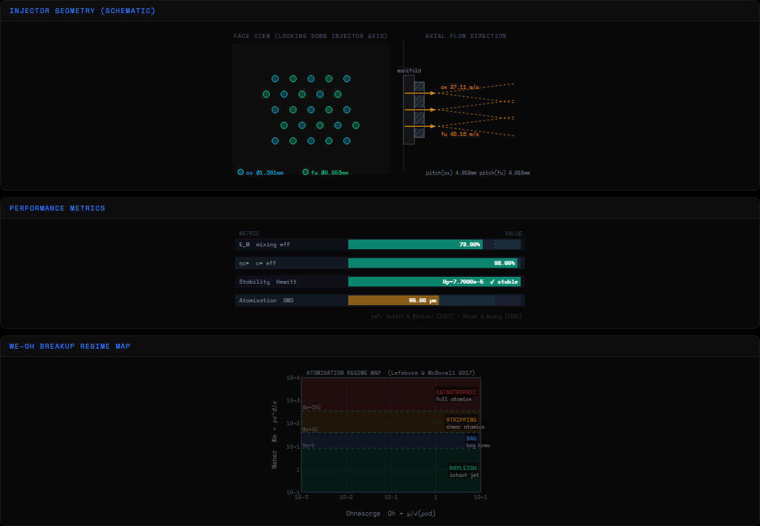
Showerhead injector diagram
Endpoint: /api/showerhead

Showerhead

Parallel, non-impinging axial holes for oxidiser and fuel. No deliberate impingement — mixing happens by turbulent diffusion downstream, which is why its mixing efficiency (E_M ≈ 0.78) trails every impinging design here.

SMD via Nukiyama-Tanasawa, v_rel = v_inj against quasi-stagnant chamber gas
  • Use case: Simplicity over performance — early test injectors, low-cost engines
  • Heritage: V-2, early gas-generator test rigs
Unlike doublet injector diagram
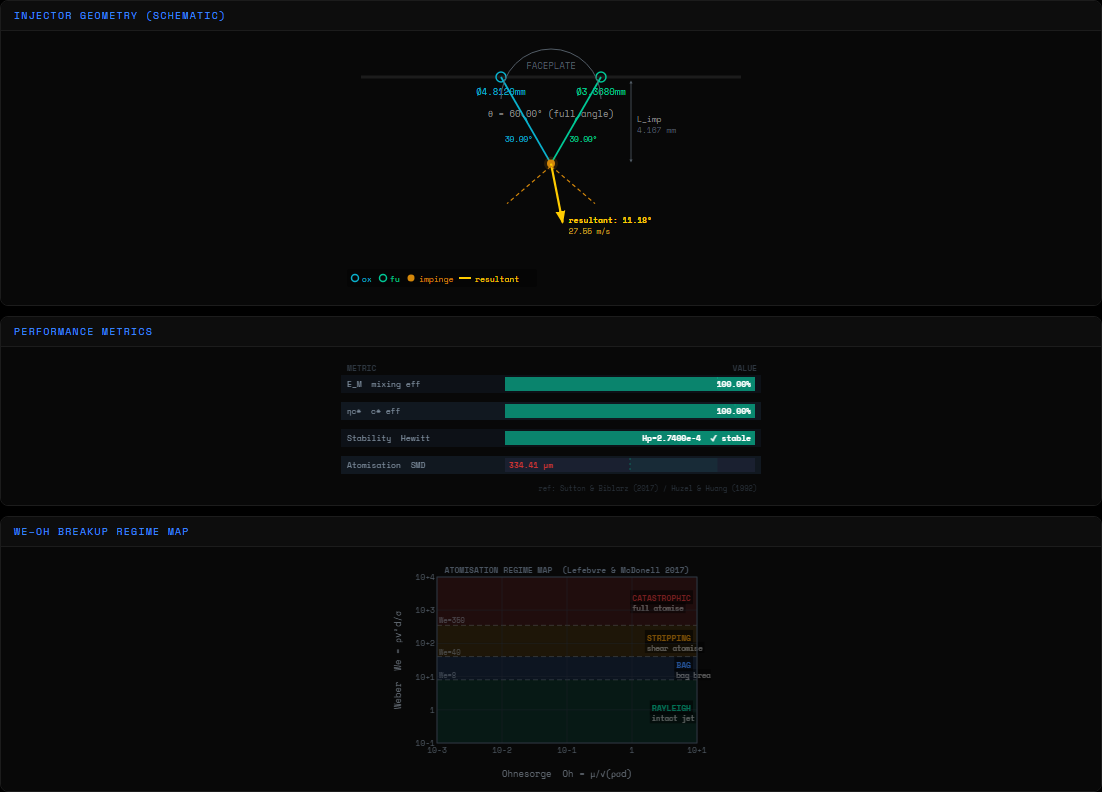
Endpoint: /api/doublet · doublet_type=unlike

Unlike Doublet

One oxidiser jet and one fuel jet impinge at a shared point. The classic injector element — momentum balance between the two jets sets whether the merged spray leaves straight down the axis or deflects off to one side.

Balance: ṁ_ox·v_ox ≈ ṁ_fu·v_fu  ·  resultant angle from momentum vector sum
  • Use case: Storable hypergolics, LOx/RP-1
  • Heritage: F-1 (Saturn V), RD-107/108
Like doublet injector diagram
Endpoint: /api/doublet · doublet_type=like_doublet

Like Doublet

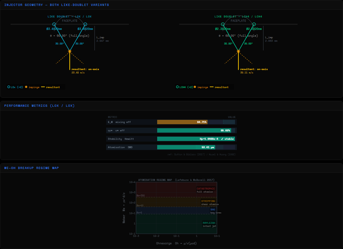
Two jets of the same propellant (ox-ox or fu-fu) impinge and split into fans; mixing with the other propellant happens between adjacent like-doublet pairs rather than within one element. Frees up faceplate layout flexibility that an unlike pair doesn't allow.

Each jet carries ṁ/2 of that propellant's element flow — symmetric split, on-axis by construction
  • Use case: Faceplate patterns needing independent ox/fu spacing control
  • Heritage: Titan/Apollo-era storable engines
Triplet injector diagram
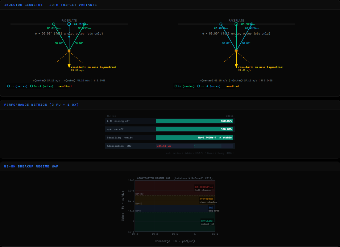
Endpoint: /api/doublet · triplet variant

Triplet

Two outer jets of one propellant converge on a single central jet of the other. Both 2-oxidiser/1-fuel and 2-fuel/1-oxidiser arrangements are computed side by side, since the momentum balance — and therefore the resultant spray angle — is completely different between them.

2·ṁ_outer·v_outer·cos(θ/2) balanced against ṁ_center·v_center
  • Use case: Aerozine-50/N₂O₄ and other storable bipropellant engines
  • Heritage: H-1, various Apollo-era storable stages
Quad injector diagram
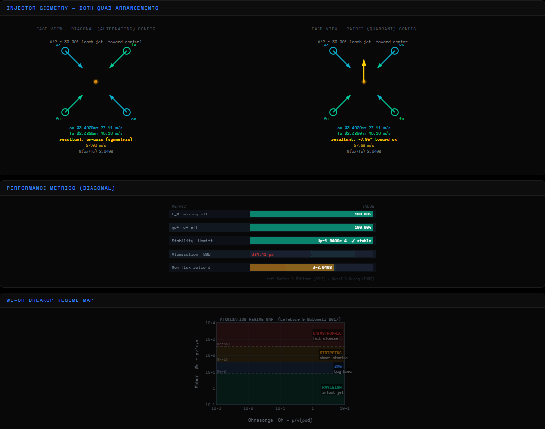
Endpoint: /api/quad · config=diagonal|paired

Quad

Four orifices per cell — two oxidiser, two fuel. The diagonal arrangement is laterally self-cancelling by symmetry no matter how unbalanced the Cd's get; the paired arrangement is not, because its two same-propellant pairs sit on opposite sides of a shared axis rather than mirrored across it — a real, derivable difference this tool actually shows as a deflected resultant vector.

Paired: p_lat = √2·sin(θ/2)·(ṁ_ox·v_ox − ṁ_fu·v_fu)
  • Use case: Higher per-cell mixing uniformity than a doublet
  • Heritage: Various Soviet-era high-density faceplates
Pentad injector diagram
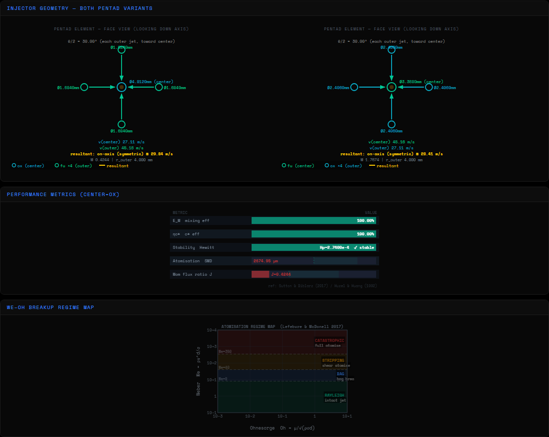
Endpoint: /api/pentad · center_is_ox=true|false

Pentad

One central orifice surrounded by four outer orifices, each tilted through half the impingement angle so all four converge with the centre jet at one common point. A generalisation of the doublet to five streams — the best per-element mixing uniformity of the whole impinging family, at the cost of the hardest faceplate to drill. Both center=ox/outer=fu and center=fu/outer=ox variants computed together.

4 outer jets + 1 center, symmetric about the axis when balanced
  • Use case: Maximum mixing uniformity per element
  • Heritage: F-1, H-1 (Saturn V first & second stage)
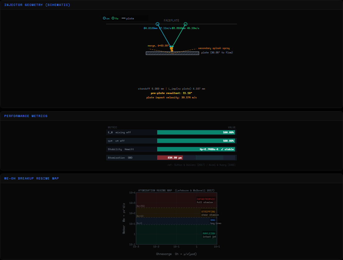
Splash plate injector diagram
Endpoint: /api/splash

Splash Plate

Two jets merge before striking a flat plate downstream — the plate provides a second atomisation event via impact, useful when faceplate geometry constrains direct jet-on-jet impingement. The merged jet's own trajectory (from the same momentum vector-sum math as the doublet) has to actually be aimed at the plate, which is a real geometric constraint this tool checks.

Merged-jet resultant angle must intersect the plate within its standoff distance
  • Use case: Constrained impingement geometry, small thrusters
  • Heritage: Various small hypergolic thrusters / RCS
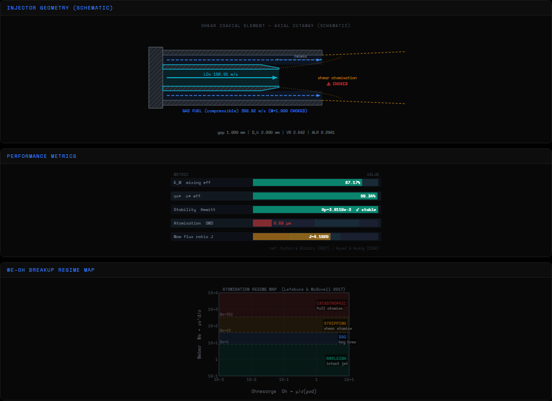
Coaxial shear injector diagram
Endpoint: /api/coaxial

Coaxial Shear

A central liquid oxidiser post surrounded by a high-velocity gas annulus. The gas strips liquid off the post surface — airblast atomisation, not impingement — and the annular gas flow is checked for choking (compressible orifice flow, Mach number, critical pressure ratio) since it's often running near sonic.

SMD/D_h = 0.48·(1+1/ALR)^0.4·We_g^-0.4·Re_l^-0.2 (Rizk-Lefebvre)
  • Use case: LOx/GH2, LOx/GCH4 — cryogenic gas-liquid pairs
  • Heritage: RS-25/SSME preburner injection, expander-cycle engines
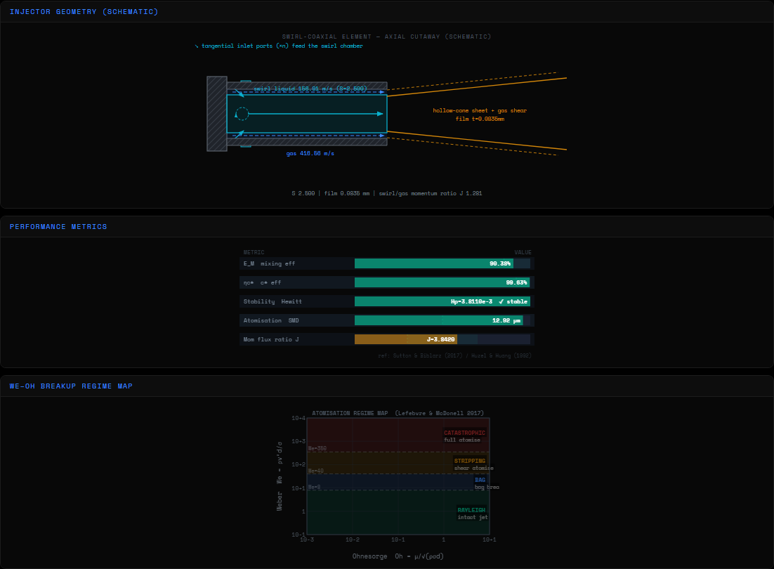
Swirl-coaxial injector diagram
Endpoint: /api/swirl_coax

Swirl-Coaxial

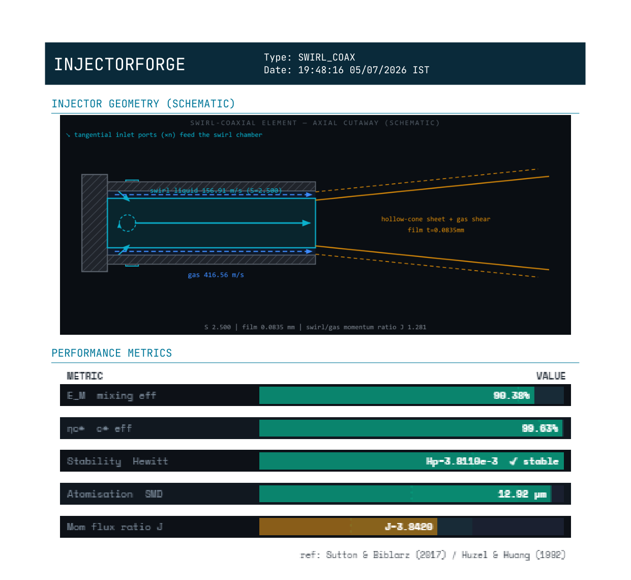
A swirled inner liquid post (usually LOx) inside an outer coaxial gas annulus — the liquid leaves as a thin, already-atomising hollow-cone sheet before the outer gas shear finishes the job. Two independent atomisation mechanisms stacked in one element, which is why staged-combustion engines lean on it so heavily.

Swirl number S sets film thickness t; outer gas shear then breaks up the resulting sheet
  • Use case: Staged-combustion, high chamber pressure engines
  • Heritage: RD-170/180, RD-0110 family
Bi-swirl injector diagram
Endpoint: /api/biswirl

Bi-Swirl

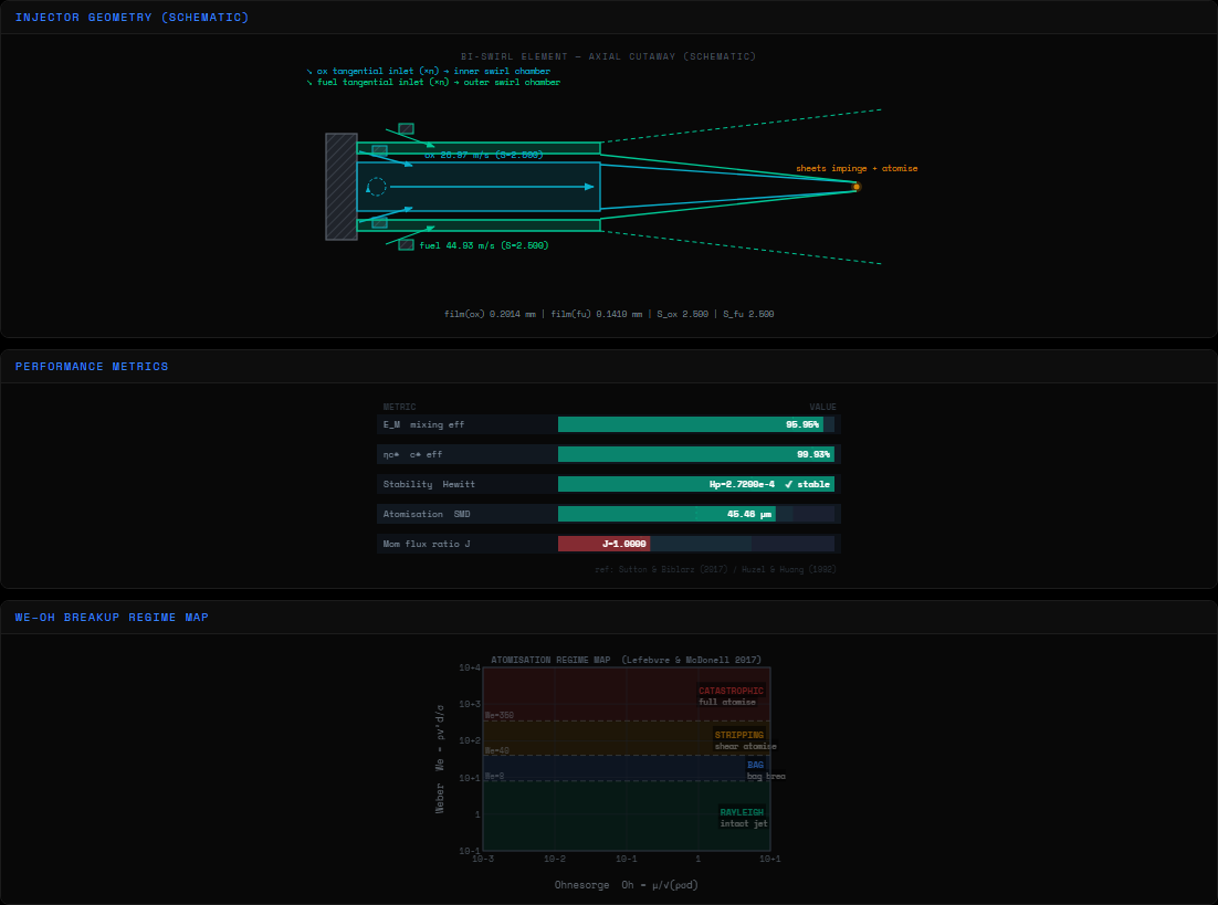
Both propellants get their own swirl insert, each producing an independent hollow-cone sheet that then impinges on the other. Fine atomisation without needing precise jet-on-jet impingement angles — useful for storable hypergolics where you want atomisation quality without doublet-style alignment sensitivity.

Spray half-angle α = atan(K/√(1−K²)), K = 1/S  (Bazarov-Yang)
  • Use case: Storable hypergolic bipropellants
  • Heritage: Viking engine (Ariane), various Soviet hypergolic stages
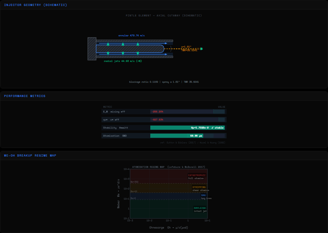
Pintle injector diagram
Endpoint: /api/pintle · φ = throttle fraction

Pintle

A single central element — an annular oxidiser sheet sheared radially by fuel jets (or vice versa) off a movable pintle tip. The only element family here with genuine deep-throttle capability: sliding the pintle sleeve changes the annular gap width, which this tool models as a continuous throttle-fraction φ from 0–1, recomputing the full throttle map on demand.

TMR = ṁ_o·v_o / (ṁ_f·v_f)  ·  gap_eff = gap_width · φ
  • Use case: Deep throttling — landers, human-rated abort-capable engines
  • Heritage: Apollo Lunar Module descent engine, Merlin 1D, TR-202
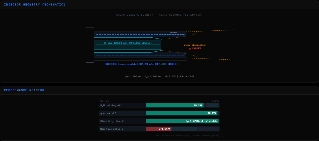
Gas-gas coaxial injector diagram
Endpoint: /api/gasgas

Gas-Gas Coaxial

Both propellants arrive already gaseous — the case for a full-flow or fuel-rich/ox-rich staged-combustion engine feeding preburner exhaust into the main chamber. No liquid-phase atomisation at all; the physics that matters here is compressible flow, choking, and turbulent gas-gas mixing rather than droplet breakup.

Compressible orifice flow both sides — Mach number & choked-flow limit checked on each
  • Use case: Full-flow / staged-combustion preburner-fed injection
  • Heritage: Raptor-class full-flow staged combustion concepts
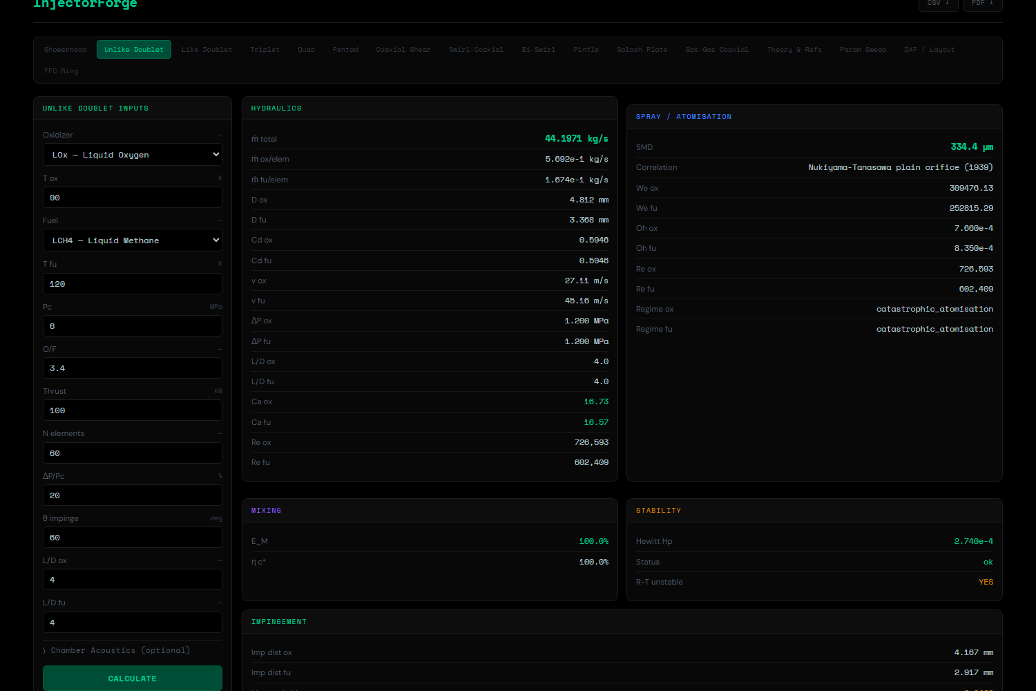
Beyond A Single Design Point

THE TOOLING AROUND THE PHYSICS

Sizing one injector element is the easy 80%. The other 20% — knowing whether your design is actually buildable, whether it's the right architecture to begin with, and getting the numbers into a format someone else can review — is where these seven features live.

01 · TOOLING
POST /api/sweep/{injector_type}

Parametric Sweep & Pareto Front

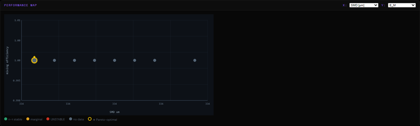
Sweeps up to three axes at once (ΔP/Pc, element count, impingement angle — up to 200 total points) against the injector type currently loaded, and plots every resulting design on a performance map you choose the axes for: SMD against mixing efficiency, stability margin against warning count, whatever trade-off actually matters for your engine.

The Pareto front is computed properly — not just "sorted by one metric" — so the points highlighted are genuinely non-dominated: no other point in the sweep beats them on every axis simultaneously. That's the actual design-space boundary, not a top-10 list.

02 · TOOLING
POST /api/sensitivity/{injector_type}

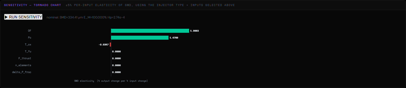
Sensitivity ("Tornado") Analysis

Central-difference finite perturbation (±5%) on every numeric input, one at a time, reporting the resulting elasticity of SMD, mixing efficiency and the Hewitt stability parameter. The output is the classic tornado chart — which input actually moves the needle, sorted longest-bar-first, so you know where to spend your tolerance budget instead of guessing.

03 · TOOLING
POST /api/layout/generate · POST /api/layout/dxf

Faceplate Layout & DXF Export

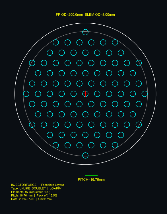
Hex-packs however many elements you need within a given faceplate OD, respecting an edge-clearance margin, and hands back both the raw (x, y) positions and packing efficiency — then, on request, an AutoCAD R2010 DXF with the faceplate boundary, every element circle, pitch/diameter dimensioning and a title block, in millimetres, ready to open in a CAD package rather than re-drawn by hand from a table of numbers.

04 · TOOLING
POST /api/report/pdf

PDF Report — Diagram-Identical Export

Most tools that export a "report" quietly regenerate the diagram server-side in a different renderer, and the PDF version subtly doesn't match what you were looking at. This one doesn't: the browser rasterises the exact SVG/canvas elements already on screen at 4× resolution and ships them to the backend, which embeds them as-is next to the full hydraulics/spray/mixing/stability tables. What you reviewed on screen is what's in the PDF, pixel for pixel.

05 · TOOLING
GET /api/heritage/list

Heritage-Engine Thermochemistry Check

Five realistic operating points named after well-documented production engines (F-1, Merlin 1D, RS-25, RD-107/108, a representative methalox point) run through this tool's own thermochemistry, and the resulting c* is checked against the same textbook propellant-pair reference table already used elsewhere as the empirical CEA fallback. This isn't a claim to reproduce any engine's exact measured flight performance — it's a sanity check that the thermochemistry is internally consistent, using a recognisable operating point instead of an arbitrary one.

06 · TOOLING
POST /api/recommend

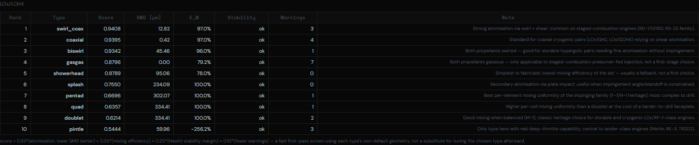
Injector-Type Recommendation Engine

Give it a propellant pair, thrust and chamber pressure, and it runs all ten applicable injector types through their own default geometry, then ranks them: 35% atomisation quality, 35% mixing efficiency, 20% stability margin, 10% fewer manufacturability warnings. It's a fast first-pass screen for "which architecture should I even be looking at," not a substitute for tuning the type you land on afterward — and it says so, in the methodology line printed with every ranking.

07 · TOOLING
core/manufacturability.py — wired into all 10 design routers

Manufacturability Screening

A design that solves mathematically isn't necessarily one a machine shop can cut. Every orifice diameter gets checked against conventional twist-drill practice (~0.3 mm) and the micro-EDM floor (~0.10 mm); every L/D against the point where a conventional drill starts to wander (~10:1); every hole pitch against the wall thickness left between adjacent holes (~0.5 mm minimum land). Violations show up as warnings right next to the physics warnings — because a hole that can't be drilled is exactly as disqualifying as a Hewitt parameter in the red.

08 · TOOLING
POST /api/ffc/design

Fuel Film Cooling (FFC) Ring

Sizes a ring of fuel-only holes near the chamber wall that diverts a fraction of total fuel flow to blanket the wall in a fuel-rich boundary layer — standard wall protection on top of whatever main injector pattern you've designed. Takes the main injector's actual total propellant flows as input, so it reports how much the diversion richens the effective core O/F, not just the FFC ring in isolation.

System Architecture

PROJECT STRUCTURE

~6,900 lines of Python across 33 files, one 3,585-line self-contained frontend, zero build step. Every file below is real — line counts taken directly from the repository, not estimated.

injector-forge/Root project directory
├── backend/FastAPI application — ~6,900 lines of Python
├── main.py61 lines — app factory, CORS, 17 router mounts, static file serving
├── core/Physics kernel — 16 files, ~2,420 lines, zero framework dependencies
├── fluid_props.py147 — CoolProp wrapper + curated fallback table (density, μ, σ) per propellant
├── cea.py141 — RocketCEA wrapper for c*/Isp/T_flame; literature-table fallback if uninstalled
├── hydraulics.py317 — orifice sizing, Lichtarowicz Cd, cavitation number, compressible orifice flow
├── atomization.py234 — SMD correlations (N-T, Rizk-Lefebvre, Lichtarowicz), We/Oh/Re, regime map
├── swirl.py165 — swirl insert geometry, film thickness, Bazarov-Yang spray cone angle
├── mixing.py142 — Rupe E_M, momentum flux ratio J, pintle TMR, bi-swirl mixing estimate
├── impingement.py102 — resultant flow-angle momentum vector sum (multi-jet elements)
├── stability.py154 — Hewitt parameter, Rayleigh-Taylor check, injection velocity ratio, Strouhal
├── evaporation.py112 — D²-law droplet evaporation → minimum combustion chamber length
├── bartz.py224 — Bartz convective heat flux, radiative flux, throat + face profile
├── manifold.py188 — supply header sizing, flow maldistribution (CoV) across elements
├── ntau.py202 — Crocco sensitive-time-lag combustion instability screening
├── manufacturability.py94 — min drill size, L/D machinability limit, hole wall-thickness check
├── heritage_engines.py57 — curated real-engine reference operating points (F-1, Merlin, RS-25...)
└── faceplate.py141 — hexagonal close-packing of N elements within a circular faceplate
├── routers/17 FastAPI routers — ~3,920 lines, one per injector type + tooling endpoint
├── showerhead.py231 — /api/showerhead
├── doublet.py307 — /api/doublet (unlike, like-doublet, triplet 2F1O/2O1F — all 4 variants)
├── quad.py248 — /api/quad (diagonal / paired configs)
├── pentad.py275 — /api/pentad (center=ox or center=fu variants)
├── splash.py220 — /api/splash
├── coaxial.py238 — /api/coaxial
├── swirl_coax.py207 — /api/swirl_coax
├── biswirl.py328 — /api/biswirl
├── pintle.py312 — /api/pintle (incl. continuous throttle-map endpoint)
├── gasgas.py237 — /api/gasgas
├── ffc.py101 — /api/ffc (fuel film cooling ring sizing)
├── sweep.py346 — /api/sweep (parametric sweep + Pareto front, all 10 types registered)
├── sensitivity.py135 — /api/sensitivity (±5% finite-difference tornado chart)
├── heritage.py56 — /api/heritage (c* vs. literature thermochemistry check)
├── recommend.py147 — /api/recommend (ranks all 10 types for a given engine)
├── dxf_export.py149 — /api/layout (hex-pack layout + AutoCAD R2010 DXF export)
└── pdf_report.py383 — /api/report (PDF export, embeds client-rasterised diagrams)
├── models/
└── schemas.py477 — every Pydantic input/output model for all 10 injector types + tooling
└── assets/fonts/
└── JetBrainsMono.ttfembedded PDF report typeface
└── frontend/Single-file HTML/CSS/vanilla JS client — no bundler, no framework
└── injector_calculator.html3,585 lines — 16 tabs, all SVG diagram rendering, all API calls, PDF/CSV/DXF export triggers