Electric Propulsion · Space Technology · Experimental Research

Advanced Ionic
Propulsion
Systems

Revolutionising space travel through efficient ion propulsion technology. From Hall Effect thrusters and gridded ion engines to an experimental miniature electron propulsion system for air and water.

Hall Effect Thruster Gridded Ion Engine FEEP Miniature EPS Wireless Control 1–200 kV DC 6th Sem: EHD + ML Auto-Tune
+HV GND HALL EFFECT THRUSTER ION BEAM → Xe propellant · 1-3 kW · Isp 1600s Xe Tank η = 65% Isp 3000 s 50,000 hr life @keyframes ionBeam { 0%,100%{opacity:0.6;} 50%{opacity:1;} }
3000+
Specific Impulse
seconds — vs ~450 s for chemical propulsion
65%
Energy Efficiency
Electrical-to-thrust conversion efficiency
50k hr
Operating Life
Typical operational lifetime of ion thrusters
Technology Survey

Types of Ion Propulsion

Three major classes of electric thruster technology — each with distinct ionisation mechanisms, specific impulse ranges, and mission suitability profiles.

TYPE 01

Hall Effect Thruster

Uses a circular discharge channel where electrons are magnetically trapped, ionising propellant gas (typically xenon). The resulting electric field accelerates ions axially to produce thrust. Known for high efficiency and moderate specific impulse in the 1–3 kW power range, making it the workhorse of modern satellite propulsion.

1–3 kW Isp 1500–2000 s High efficiency Xe propellant
TYPE 02

Gridded Ion Engine

Features two or three closely spaced biased grids that extract and electrostatically accelerate ions from the discharge chamber. Delivers very high specific impulse and excellent propellant utilisation efficiency, making it the preferred choice for deep space missions requiring precise, sustained thrust over years.

Isp 3000+ s High Isp Deep space Electrostatic
TYPE 03

FEEP Thrusters

Field Emission Electric Propulsion uses liquid metal — typically indium or caesium — as propellant. A strong electric field extracts ions directly from the liquid metal surface. Provides extremely precise, micro-Newton-level thrust control, ideal for drag-free gravitational science missions and precision formation flying.

Micro-Newton Precision control In / Cs propellant Science missions
Mission Applications

Where Ion Propulsion Excels

Three operational domains where the high specific impulse and low thrust of electric propulsion provide decisive mission advantages over chemical alternatives.

🛰️

Satellite Station-Keeping

Maintains precise orbital positions for communication and navigation satellites with minimal propellant consumption. A single ion thruster can extend satellite operational life by years compared to a chemical system carrying equivalent mass.

🚀

Deep Space Missions

Provides continuous, efficient thrust for interplanetary travel and deep space exploration. Dawn, Hayabusa, and BepiColombo all rely on ion propulsion to achieve trajectories that would be propellant-prohibitive for chemical engines.

🔄

Orbital Transfers

Enables efficient plane changes and altitude transfers for commercial satellite operators. Electric orbit raising from GTO to GEO has become economically attractive for high-power communications satellites, reducing launch mass significantly.

1st Semester Project · RVCE

Miniature Electron Propulsion System

An experimental investigation into developing a compact ionic thruster optimised for air and water propulsion — with a miniature ionic-propelled boat as proof-of-concept demonstrator. Built in my first semester as an early hands-on introduction to electrohydrodynamic propulsion; see the 6th semester IDP project below for the full physics-informed, ML-controlled successor.
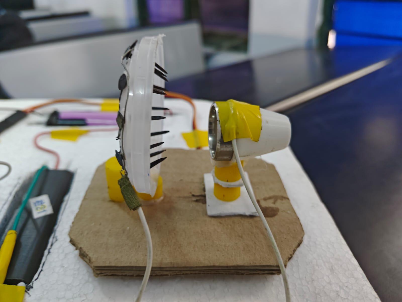
Custom Electrode Configuration
Side View — Ionic Propulsion Assembly

Custom electrode geometry designed to generate a high-voltage ionic wind field. Configuration optimised for maximum thrust-to-weight ratio at the target operating voltage range.
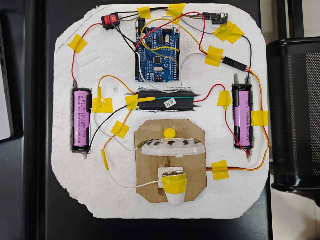
Boat Platform
Top View — Boat Configuration

Compact modular hull designed to demonstrate ionic propulsion in water medium. Minimal form factor with integrated direction control and wireless interface.

Remote Control Interface Demo

Wireless RC Interface · Live Demo

Phone Control Interface Demo

Smartphone Control · Live Demo

Test Fire Sequence

Thruster Test Fire · Thrust Characterisation
Technical Data

System Specifications

Measured and estimated parameters from the experimental miniature electron propulsion thruster demonstrator.

Electrical & Thrust Parameters
  • Operating Voltage1 – 200 kV DC (transformer/booster dependent)
  • Current Draw100 – 500 μA
  • Thrust5 – 10 mN
  • Operating MediumAir (primary); Water (boat demonstrator)
  • Ionisation MethodField emission / corona discharge
Design Features
  • Electrode ConfigCustom geometry for maximum ionic wind generation
  • Control InterfaceWireless RC + smartphone app
  • Direction ControlIntegrated directional thrust vectoring
  • ArchitectureModular component design for scalability
  • Form FactorCompact, optimised for minimal footprint

Successful electron movement and ion generation confirmed via visible corona discharge

🎯

Stable thrust production measured in the 5–10 mN range across operating voltage envelope

📡

Remote wireless operation demonstrated via both RC interface and smartphone control

📐

Scalable design architecture validated — modular components allow thrust level adjustment

Full proof-of-concept validation: ionic thrust in air and water medium achieved

🔧

Custom nozzle design fabricated and tested for improved ion beam directionality

6th Semester Project · Interdisciplinary Project (IDP), RVCE

Physics-Informed ML for EHD Ionic Wind Thruster Modelling with Closed-Loop Control

A fully integrated ionic thruster research platform — precision hardware fabrication, high-voltage power electronics, real-time monitoring, and machine-learning-based auto-tuning — benchmarked against established experimental literature. This is the direct successor to the 1st semester boat thruster above, rebuilt from first principles as a rigorous, closed-loop research system.

Team CP-19 — Nidhi Kulkarni (1RV23CS151) · Mrida Pradhan (1RV23CD030) · Shanthosh KV (1RV23AS053) · Kaushal H (1RV23EC066)
Mentor — Dr. Jyoti Shetty

0.997
Current Prediction
XGBoost regressor, MAPE 11.60% on unseen electrode geometries
1.00F1
Corona-Onset Classifier
Random Forest gate — perfect accuracy/precision/recall on held-out geometries
2.1mN
Peak Measured Thrust
±0.2 mN at 2 cm gap, 30 kV — efficiency 0.040 mN/W
Problem Statement

Why Ionic Thrusters Need Intelligent Control

Current ionic-thruster research faces three compounding challenges that motivate this project.

Three Key Challenges
  • Efficiency unpredictabilityThrust is highly sensitive to electrode geometry, gap distance, and applied voltage — manual optimisation is tedious and inconsistent
  • Safety riskOperating voltages of 20–40 kV demand robust protection most prototype setups lack
  • No intelligent controlExisting systems use fixed operating points with no adaptive feedback, leaving performance potential unrealised
Objectives
  • 013D-printed PLA thruster frame, wire emitter / flat-plate collector, 2–5 cm adjustable gap
  • 02ZVS flyback driver + 15-stage Cockcroft–Walton multiplier → 20–40 kV DC with hardware safety cutoffs
  • 03Python GUI: real-time V/I monitoring, PWM control, live plotting, CSV session logging
  • 04Gaussian Process Regression on experimental PWM–V–I–thrust data, integrated as an autonomous auto-tune module
  • 05Quantify thruster performance; plot thrust vs. voltage curve
Literature Survey

From Gilmore (2015) to Sawtooth Multi-Ring (2025)

Every prior study leaves the same gap open: no closed-loop, ML-driven control of an integrated ionic thruster system. The MIT Nature paper (Xu, He & Barrett, 2018) — first solid-state aircraft flight — is the project's anchor reference.

Selected literature and identified research gaps
Year Title / Authors Research Gap
2015 EHD thrust density via positive corona · Gilmore & Barrett No multistage design, sensing, feedback, or autonomous control
2018 Flight of an aeroplane with solid-state propulsion · Xu, He, Strobel, Gilmore, Perreault, Barrett (Nature 563) — anchor reference No closed-loop control, no onboard sensing, fixed electrode geometry
2019 Higher thrust-to-power with large gap spacing · Xu, Gomez-Vega, Agrawal, Barrett No adaptive gap optimisation — fixed manual voltage setpoints
2021 Decoupled EAD thrusters · Gomez-Vega, Xu, Abel, Barrett No embedded controller for dual HV supplies in closed loop
2022 Mitigating reverse emission · Gomez-Vega, Kambhampaty, Barrett Only passive geometric fixes — no dynamic electrical control
2024 ML-enabled plasma modelling · Farbod, Maryam, Aaron (AIAA SciTech) Offline modelling only — no trained model deployed in an embedded control loop
2025 Sawtooth multi-ring electrodes · Hou et al. (Scientific Reports) — 28.2% thrust-density gain Optimal voltage tuned manually per geometry — no surrogate model
Methodology

Four-Phase System Pipeline

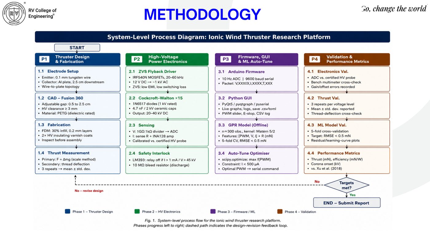
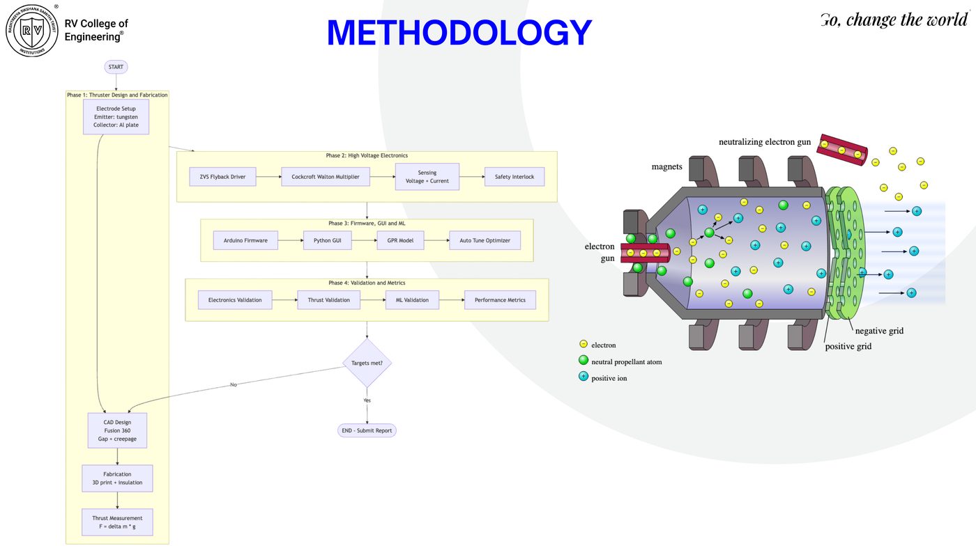
Thruster design & fabrication → high-voltage power electronics → firmware/GUI/ML → validation & metrics — with a design-revision feedback loop when targets aren't met.

Methodology flowchart and EHD thruster schematic
Process flow + EHD schematic. Wire emitter → collector grid: neutral propellant atoms are ionised, accelerated across the field, and neutralised downstream, dragging surrounding air to produce ionic wind.
System-level process diagram: P1 thruster design, P2 HV electronics, P3 firmware/ML, P4 validation
System-level process diagram. P1 Thruster Design & Fabrication → P2 High-Voltage Power Electronics → P3 Firmware, GUI & ML Auto-Tune → P4 Validation & Performance Metrics.
Hardware · CAD Design

Electrode Frame Iteration & Fabrication

Fusion 360 / SolidWorks CAD, FDM-printed in PETG (30% infill, 0.2 mm layers, 2× HV insulating varnish). Wire-to-plate topology, adjustable 0.5–2.5 cm gap, ≥3 mm HV clearance.

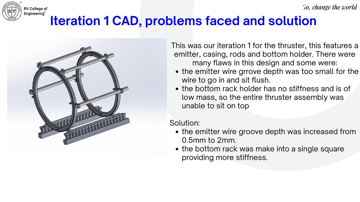
Iteration 1 CAD — emitter groove and bottom rack too shallow/weak
Iteration 1 — problems found. Emitter wire groove too shallow (0.5 mm) for the wire to sit flush; bottom rack lacked stiffness. Fix: groove deepened to 2 mm; bottom rack unified into a single rigid square.
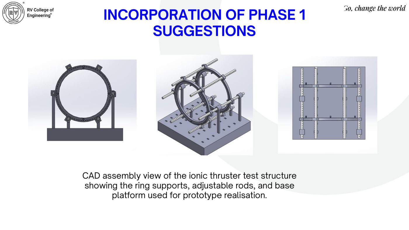
Incorporation of phase 1 suggestions — final ring supports, rods, base platform
Revised assembly. Ring supports, adjustable rods, and a rigid base platform for prototype realisation.
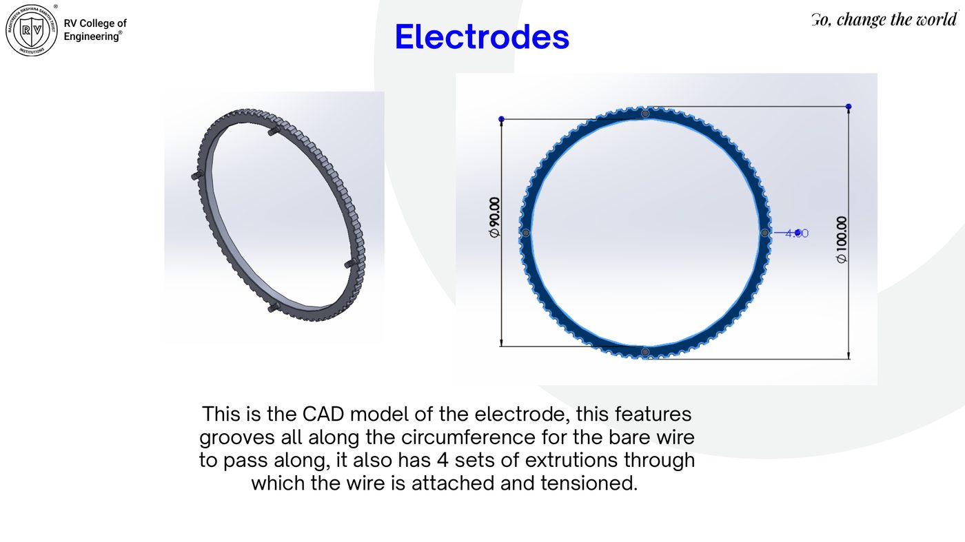
Electrode CAD — grooved ring, Ø100mm outer / Ø90mm inner, 4 tensioning points
Electrode ring. Ø90–100 mm, grooved circumference for the bare emitter wire, 4 tensioning extrusions.
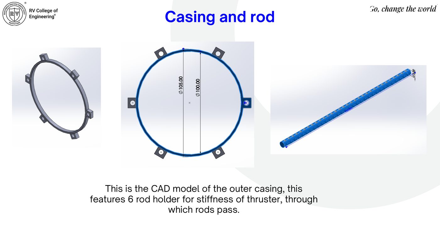
Outer casing with 6 rod holders and connecting rod
Casing & rod. Ø100–105 mm outer casing, 6 rod holders for structural stiffness.
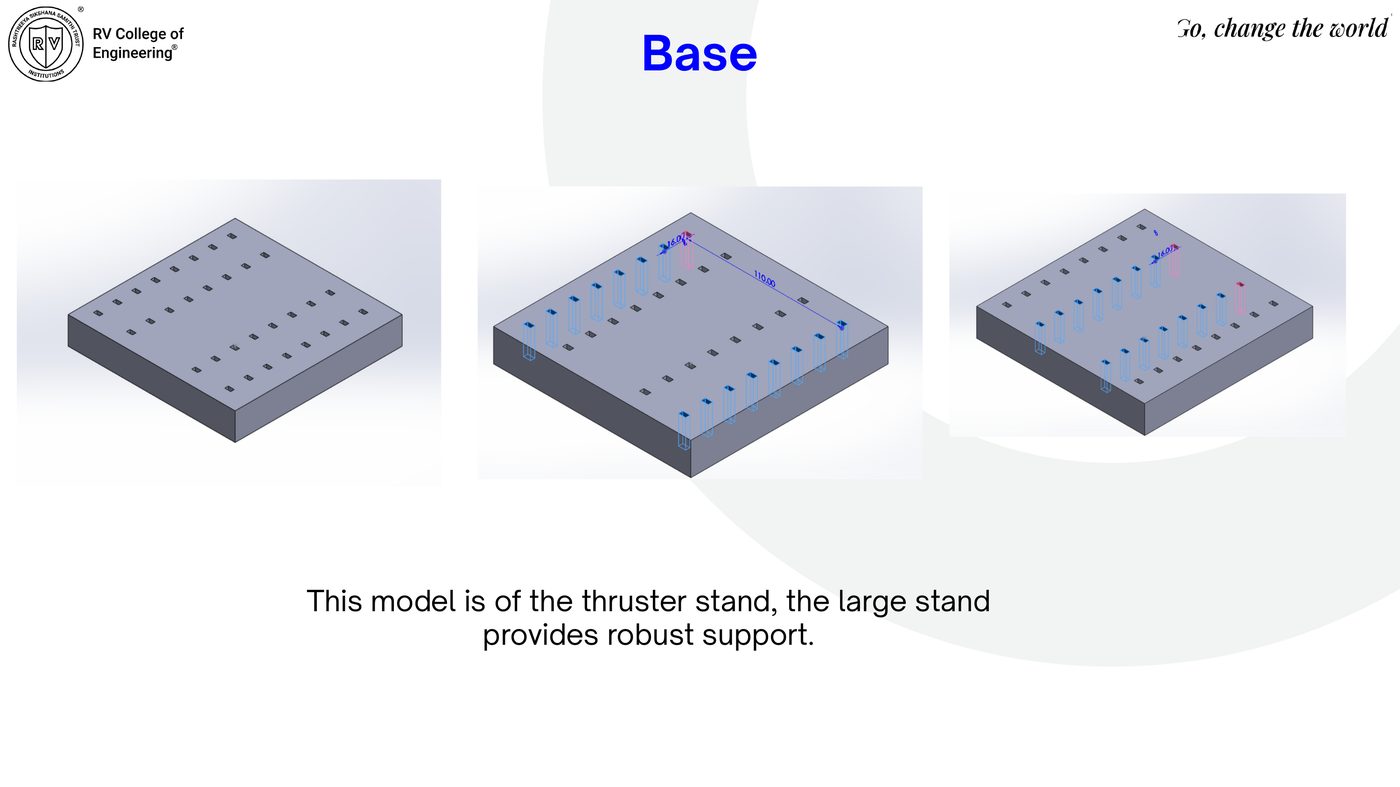
Thruster stand base plate with mounting holes
Base / stand. Large-footprint base plate for robust support of the full assembly.
Governing Physics

Peek, Townsend & Stuetzer Ion-Drag

Corona onset (Peek's Law) gates a Townsend quadratic discharge-current model, which feeds the Stuetzer ion-drag relation for thrust, power/efficiency, and momentum-flux ionic wind velocity.

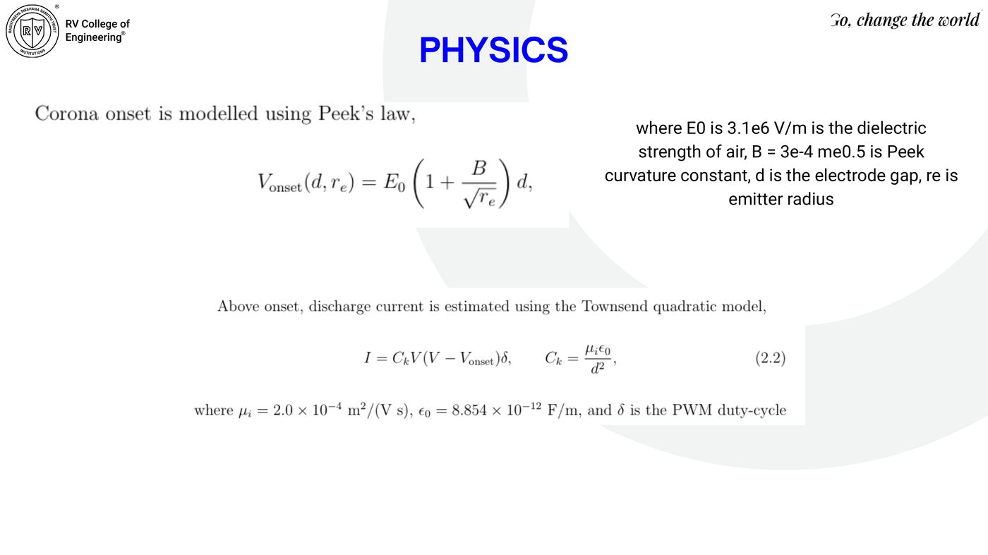
Peek's law for corona onset voltage and Townsend quadratic discharge current model
Onset & current. Vonset(d, re) = E₀(1 + B/√re)d, with E₀ = 3.1×10⁶ V/m, B = 3×10⁻⁴ m^0.5. Current: I = CkV(V − Vonset)δ, Ck = μᵢε₀/d², μᵢ = 2.0×10⁻⁴ m²/(V·s), δ = PWM duty cycle.
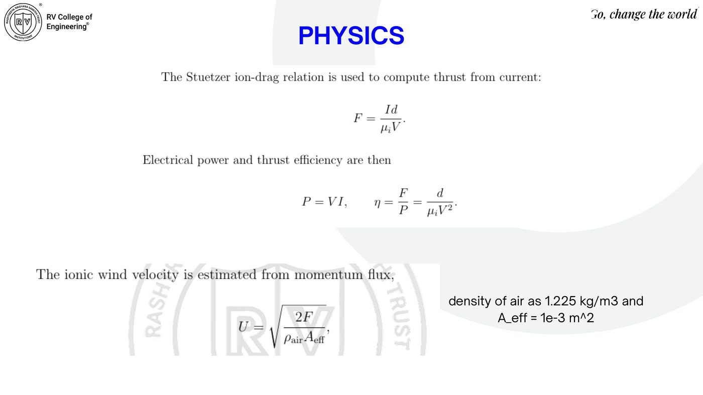
Stuetzer ion-drag thrust relation, power, efficiency, and momentum-flux velocity
Thrust, power, velocity. F = Id/(μᵢV); P = VI; η = F/P = d/(μᵢV²); ionic wind velocity U = √(2F/(ρairAeff)), ρair = 1.225 kg/m³, Aeff = 1×10⁻³ m².
High-Voltage Electronics

ZVS Flyback + 15-Stage Cockcroft–Walton

IRF540N ZVS flyback driver (12 V → ~1 kV AC, 20–60 kHz) feeding a 15-stage Cockcroft–Walton multiplier (1N6517 diodes, 4.7 nF/2 kV ceramic caps) for 20–40 kV DC output, with LM393 comparator hardware safety interlock (relay trips at I > 1 mA or V > 45 kV) and a 10 MΩ bleed resistor.

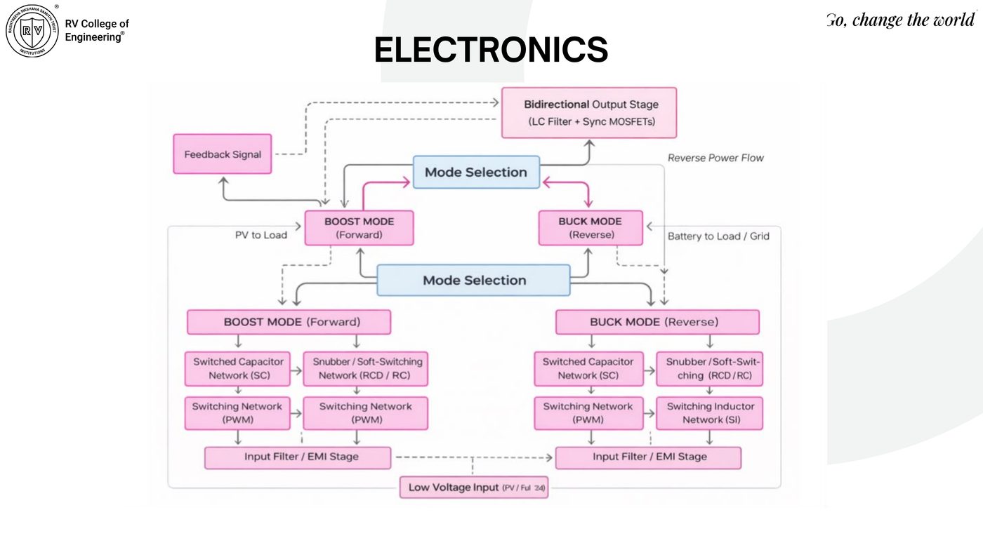
Boost/buck mode selection block diagram with switched capacitor and switching inductor networks
Mode-selection topology. Bidirectional boost/buck stages with switched-capacitor and switching-inductor networks feeding a common LC-filtered output.
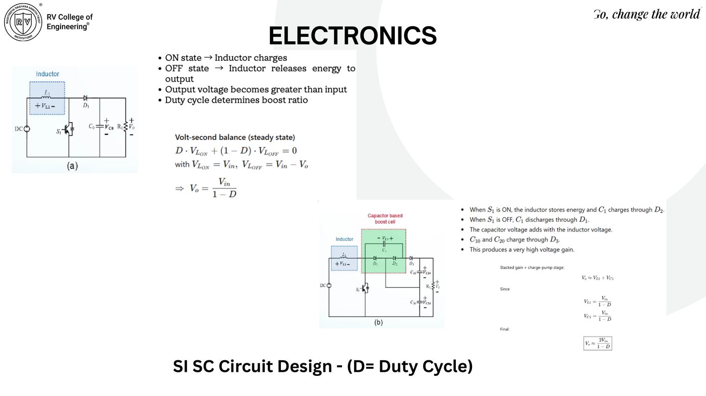
SI/SC boost converter circuit with volt-second balance derivation, Vo = Vin/(1-D) and stacked gain Vo ≈ 2Vin/(1-D)
SI/SC boost cell (D = duty cycle). Volt-second balance gives V₀ = Vin/(1−D); the capacitor-based boost cell stacks gain to V₀ ≈ 2Vin/(1−D).
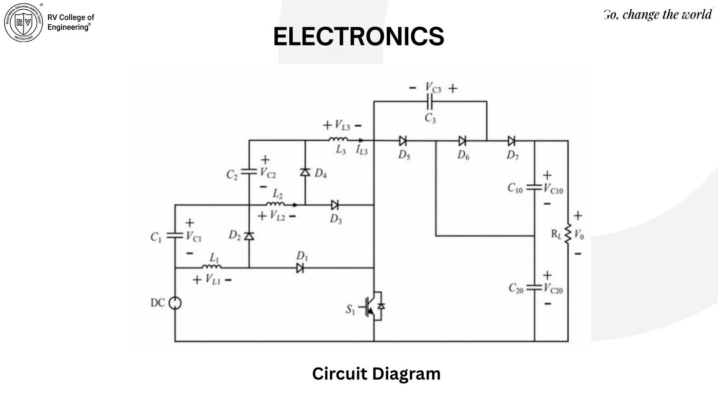
Full three-stage switched-inductor switched-capacitor multiplier circuit diagram
Full multiplier circuit. Three cascaded L–D–C stacked-gain stages (L₁–L₃, D₁–D₇, C₁–C₃, C₁₀/C₂₀) driving the load.
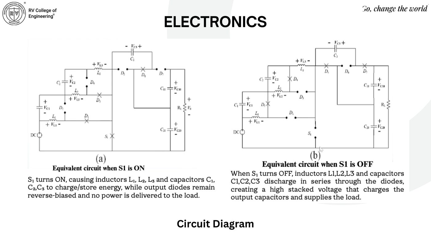
Equivalent circuits when switch S1 is ON versus OFF, showing energy storage and series discharge
S1 ON vs. OFF. ON: L₁–L₃/C₁–C₃ charge, output diodes reverse-biased. OFF: inductors and capacitors discharge in series through the diode chain, producing the stacked HV output.
Machine Learning · Datasets

Two-Stage Pipeline: Classifier Gate + Regressor

A Random Forest corona-onset classifier gates physically-impossible sub-threshold predictions; an XGBoost regressor then predicts current, from which thrust, power, and velocity are derived analytically.

Datasets
Dataset Samples Composition
DS1 9,721 2,285 corona-active (23.5%), 7,436 inactive (76.5%) — motivates the classifier gate
DS2 16,088 7 features across 5,504 geometry groups — VkV, dmm, re,mm, PWMpct measured; Vonset,kV, ΔVkV, V/Vonset engineered from first principles. Train 12,888 / test 3,200 rows, zero geometry leakage.
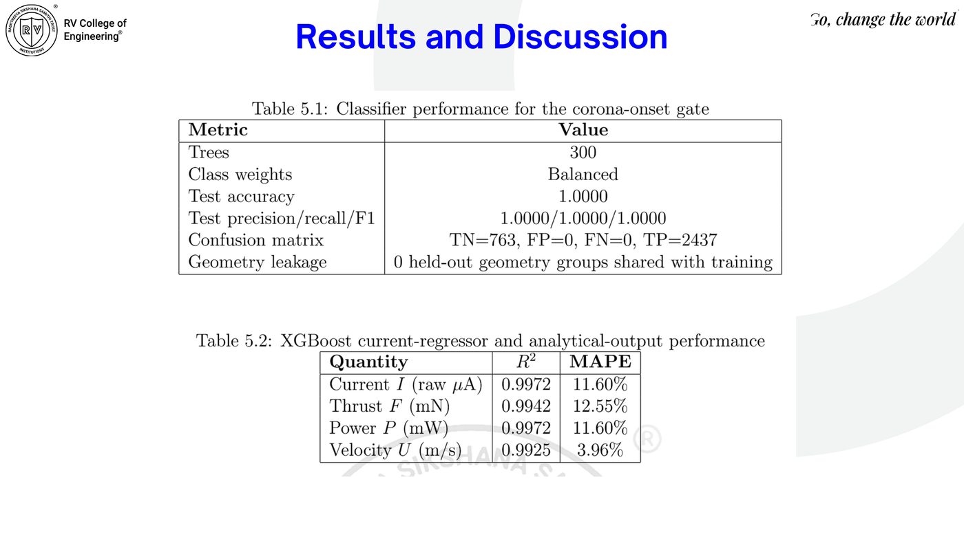
Table 5.1 — Classifier performance (corona-onset gate)
Trees 300
Class weights Balanced
Test accuracy / precision / recall / F1 1.0000
Confusion matrix TN 763, FP 0, FN 0, TP 2437
Geometry leakage 0 held-out groups shared with training
Table 5.2 — XGBoost regressor performance
Quantity MAPE
Current I (raw µA) 0.9972 11.60%
Thrust F (mN) 0.9942 12.55%
Power P (mW) 0.9972 11.60%
Velocity U (m/s) 0.9925 3.96%
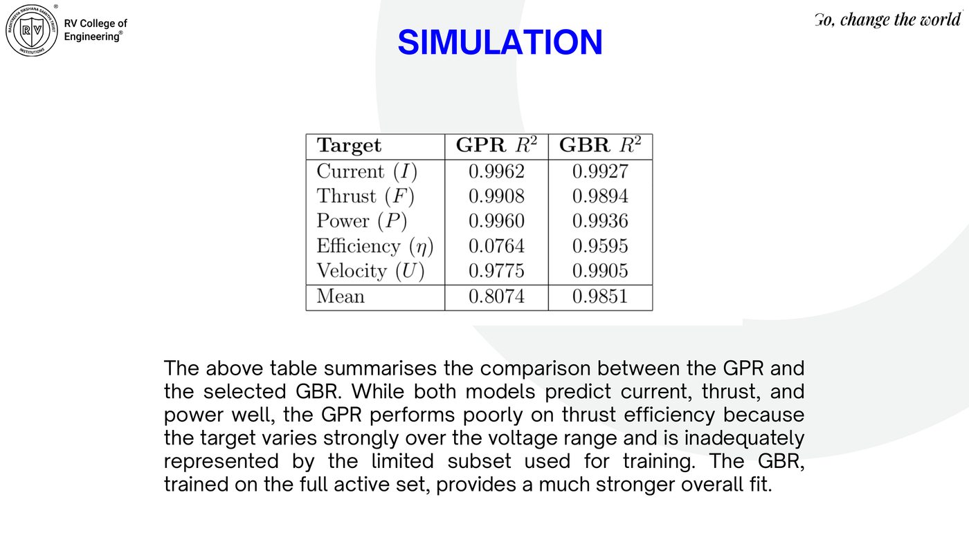
GPR vs. GBR — mean R² across all five targets (current, thrust, power, efficiency, velocity)
Target GPR R² GBR R²
Current (I) 0.9962 0.9927
Thrust (F) 0.9908 0.9894
Power (P) 0.9960 0.9936
Efficiency (η) 0.0764 0.9595
Velocity (U) 0.9775 0.9905
Mean 0.8074 0.9851
Ionic thrust simulation dashboard — current, thrust, efficiency, ionic wind velocity, and 3D thrust surface vs applied voltage and electrode gap
Simulation dashboard (10 mm gap, 0.05 mm emitter radius, 80% duty cycle). Corona onset at 32.32 kV; peak efficiency 50.0% at 32.4 kV; at 40 kV: 12.35 mA, 0.010 mN thrust, 0.494 W, 0.145 m/s ionic wind. Thrust increases with voltage and decreases with larger gap; efficiency peaks at an optimal voltage then falls.
Hardware / Software Demonstration

SIL, HIL & Physical Prototype

Layered validation: SciPy SLSQP auto-tuner running against a real XGBoost inference engine (SIL), an Arduino/ESP32 + Wokwi hardware-in-the-loop bridge streaming live V/I/T telemetry at 10 Hz, and a physical wound-electrode prototype driven by a DC-DC booster.

Wound electrode prototype and ESP32 dev board
Physical build. Wound-wire electrode assembly on a 3D-printed frame; ESP32 board for sensing and serial comms.
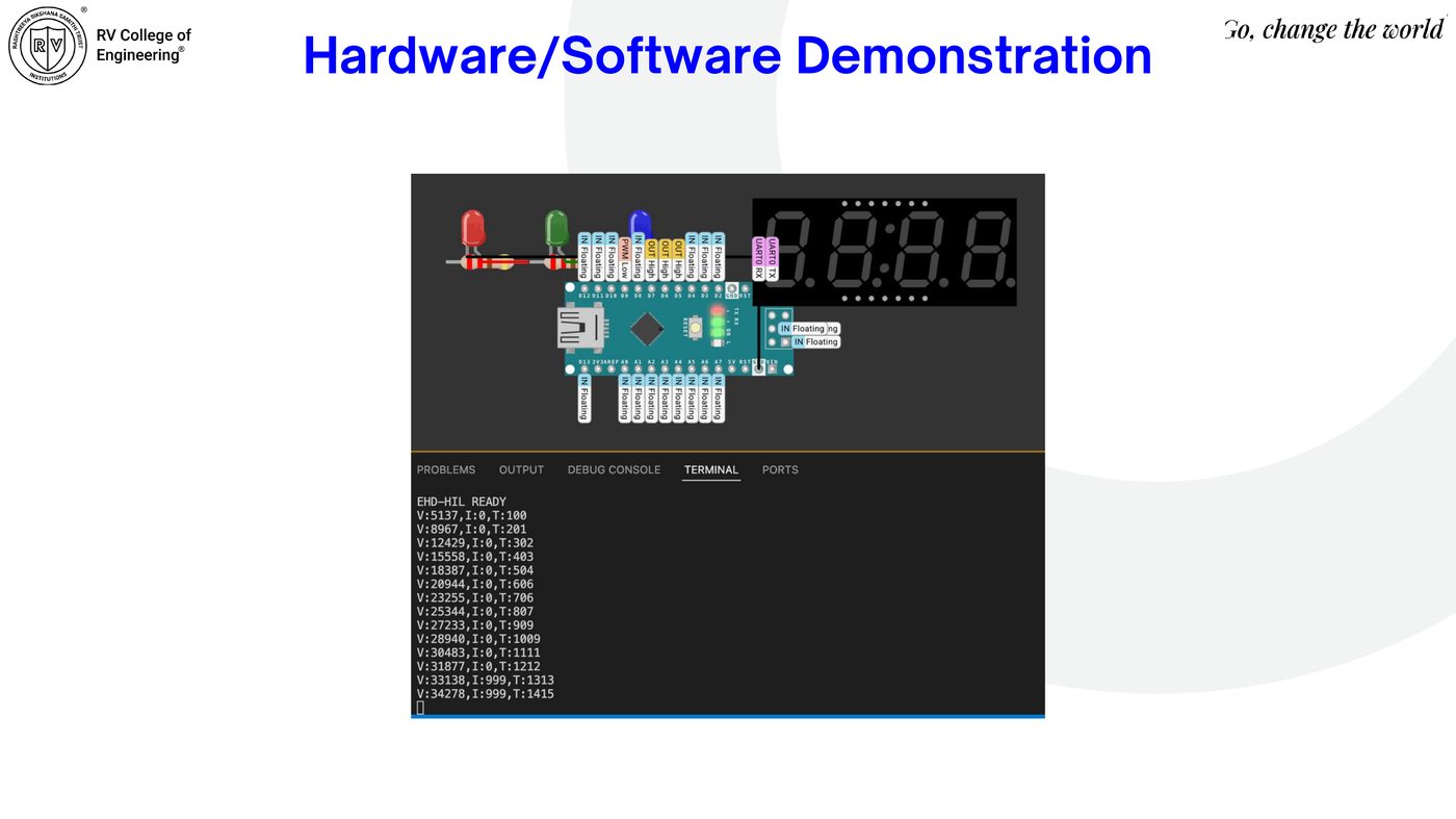
Wokwi HIL simulation with Arduino Nano and serial terminal streaming V,I,T telemetry
HIL bridge (Wokwi). Arduino Nano streaming V,I,T telemetry packets at 10 Hz over serial — firmware, protocol, and inference confirmed as a unified closed loop.
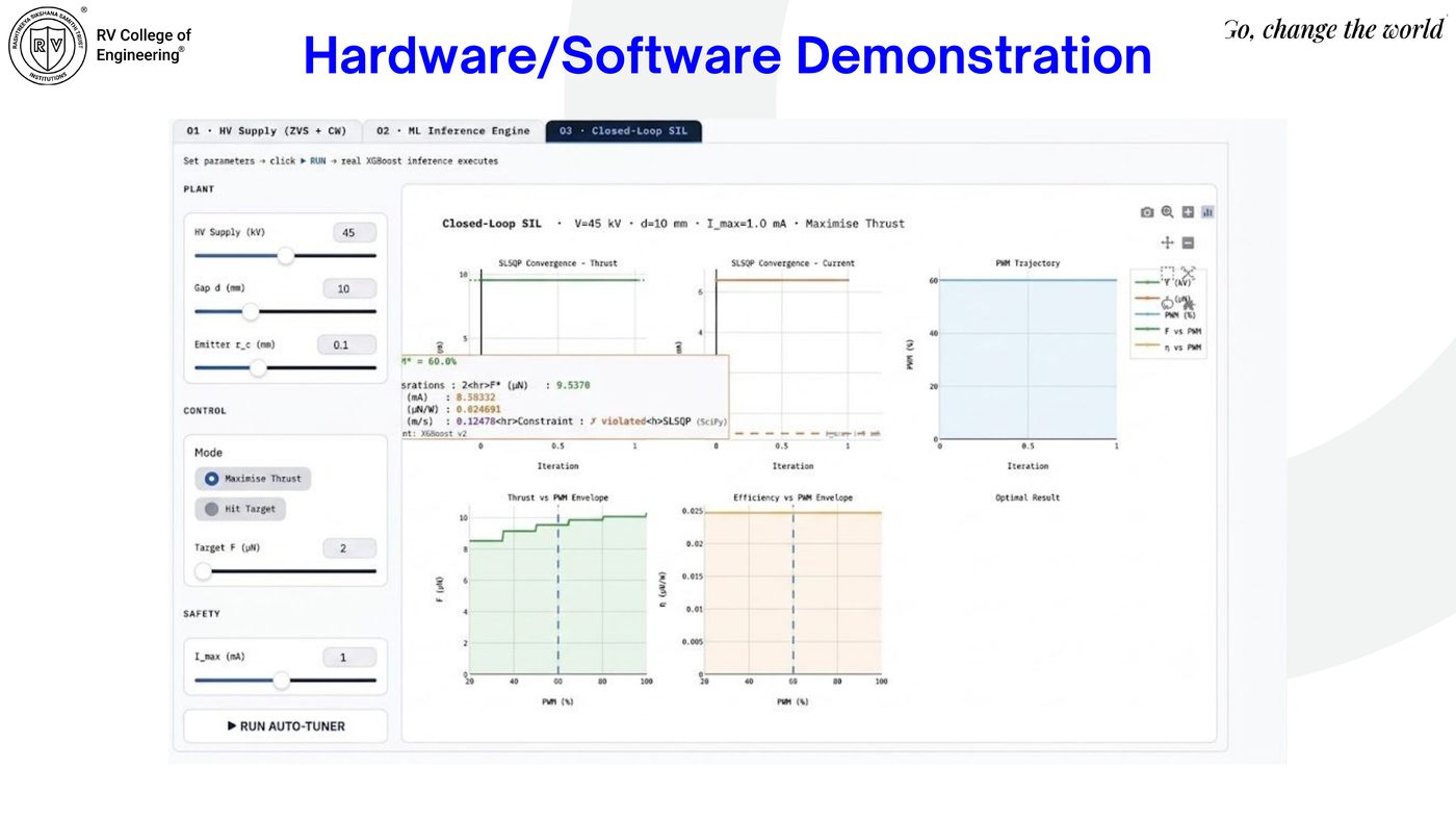
Closed-loop SIL dashboard with SLSQP convergence plots for thrust and current
Closed-loop SIL. SLSQP auto-tuner converging in 2–5 iterations (<500 ms) at 45 kV, 10 mm gap, Imax = 1.0 mA, maximise-thrust mode.
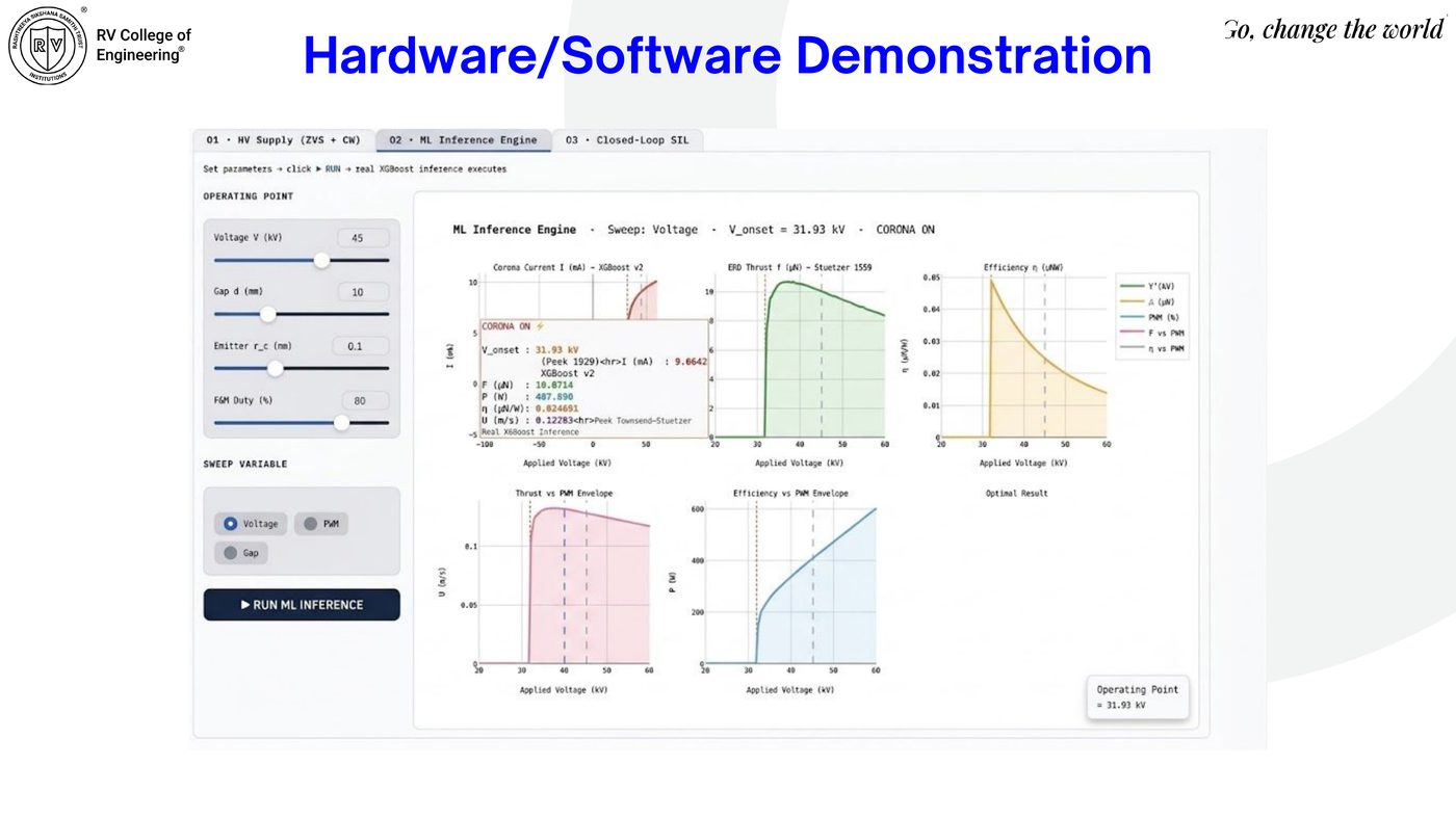
ML inference engine dashboard sweeping voltage — current, thrust, efficiency vs applied voltage
ML inference engine. Real XGBoost inference sweeping voltage — corona onset at 31.93 kV, live current/thrust/efficiency/velocity curves.
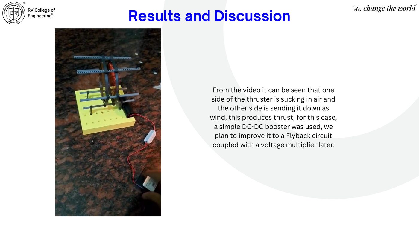
Physical thruster prototype connected to DC-DC booster during test
Test fire. One ring draws air in, the other expels it as ionic wind, producing measurable thrust — driven here by a simple DC-DC booster (Flyback + multiplier planned next).
Results & Discussion

Consistent Across Equations, Data, Sim & Hardware

Physics checks, SIL, HIL, and physical measurements form a layered validation pathway for closed-loop ionic wind control.

Table 5.3 — Measured thrust performance at 30 kV
Gap (cm) Thrust (mN) Power (W) Efficiency (mN/W)
2.0 2.1 ± 0.2 52.4 0.040
3.0 1.3 ± 0.1 48.1 0.027
4.0 0.7 ± 0.1 44.6 0.016
5.0 0.3 ± 0.1 41.2 0.007
AI-driven performance prediction and optimisation summary poster — corona state detection, current prediction, derived outputs, auto-tuner performance, experimental peak thrust
Full results summary. Perfect corona-state detection, R² = 0.9942–0.9972 derived-output predictions on unseen geometries, <500 ms auto-tuner convergence (10 Hz-compatible), 2.1 ± 0.2 mN peak experimental thrust at 2 cm gap.
Applications

Beyond the Lab Bench

🖥️

Electronics & Chip Cooling

Silent, vibration-free airflow over PCBs and power electronics — no moving parts, no mechanical failure. Studied by Intel and academic groups as a fan replacement in confined enclosures.

🛩️

Indoor Micro-UAVs

At gram-scale payload, ionic thrusters compete with rotary propellers — silent, no exposed blades, ideal for inspection drones inside buildings and pipelines.

🌬️

Aerodynamic Flow Control

EHD actuators suppress boundary-layer separation on wings, reducing drag 5–15%. Boeing and Airbus research divisions already use DBD/corona actuators on wind-tunnel models.

🛰️

Spacecraft Thermal Management

In vacuum or near-vacuum habitats, ionic wind circulates coolant gas with zero mechanical parts — critical for long-duration deep-space missions.

💨

Air Purification & Ionisers

Corona discharge simultaneously generates ionic wind and reactive oxygen species that neutralise airborne pathogens — the principle behind commercial ionic air purifiers.

💧

Electrostatic Precipitation

High-voltage DC ionises airborne water vapour; ions aggregate at a grounded collector into droplets — a candidate approach for water-scarce regions.

Conclusion

Results, Limitations & Future Work

Results Achieved
  • Physics-informed two-stage ML pipeline: R² = 0.9972 current prediction, F1 = 1.0000 corona-state classification on unseen geometries
  • Closed-loop control validated end-to-end through SIL (SLSQP, Gradio dashboard) and HIL (Arduino Nano, Wokwi, Python bridge)
  • Experimental prototype: 2.1 ± 0.2 mN peak thrust at 30 kV, gap-dependent trend consistent with the governing EHD equations
Limitations & Future Work
  • Limitation: synthetic dataset — not yet retrained on large-scale physical data; ZVS-CW supply validated only in MATLAB simulation; peak efficiency remains low (0.040 mN/W), typical of single-stage atmospheric EHD thrusters
  • Next: retrain on experimental data capturing humidity/erosion/recirculation effects
  • Next: adopt multi-stage ducted geometries to raise thrust density
  • Next: migrate inference + SLSQP optimiser onto an embedded platform for fully self-contained onboard control
Project Timeline

16-Week Build Schedule

16-week Gantt chart covering literature review, CAD, fabrication, electronics build, firmware/GUI, integration, ML training, and reporting
Literature review & CAD (W1–4) → electronics + firmware/GUI (W3–9) → system integration, experimental data & ML training (W9–14) → auto-tune integration, reporting & final demo (W11–16).
Outcome

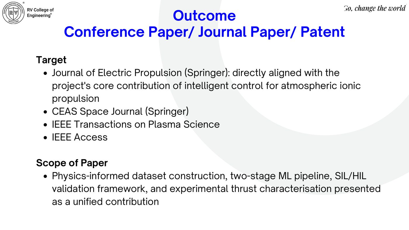
Target: Journal Publication

Physics-informed dataset construction, two-stage ML pipeline, SIL/HIL validation framework, and experimental thrust characterisation, presented as a unified contribution.

Journal of Electric Propulsion (Springer) CEAS Space Journal (Springer) IEEE Transactions on Plasma Science IEEE Access