Real surfaces aren't smooth — manufacturing tolerances, ablation, erosion, and wear roughen them up. This asks whether that roughness, modeled as an equivalent sand-grain height rather than resolved geometry, measurably shifts the oblique shock angle on a supersonic double-wedge.
- M 2.73freestream
- k-ω SSTturbulence model
- 1e-3 mmproduction first-layer height
- 0.6/0.8/0.9mm sand-grain cases
Why a double wedge
One 2D geometry produces all three flow features of interest in a single run: an attached oblique shock at the leading edge (compression), a Prandtl–Meyer expansion over the mid-chord, and a trailing recompression shock.
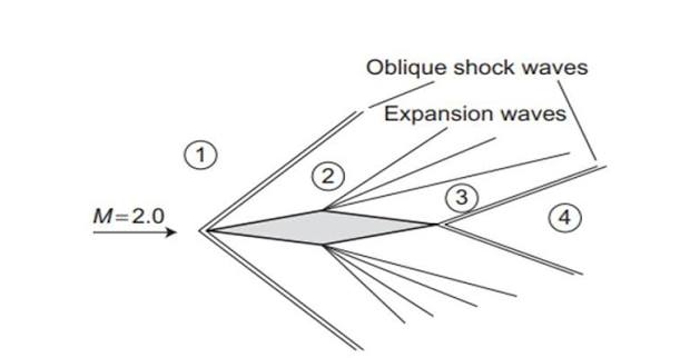
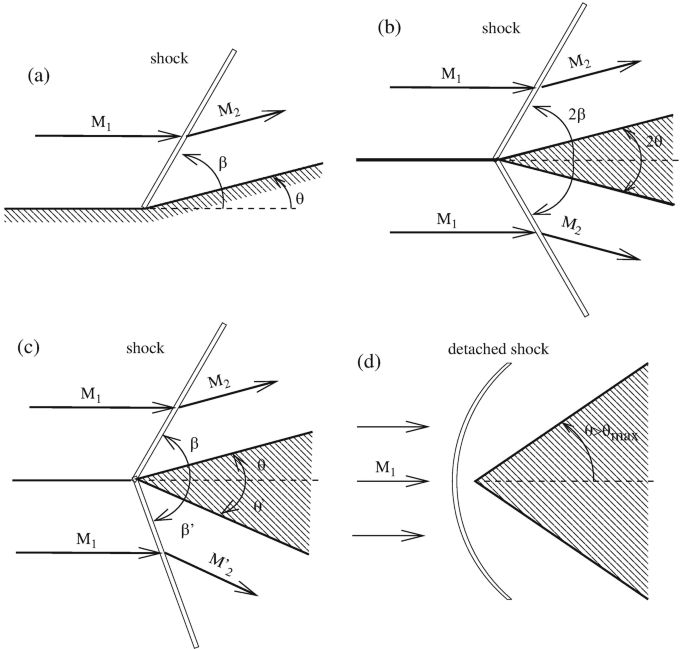
Analytical baseline (smooth wall) comes from the standard oblique-shock relation tan θ = 2 cot β · (M₁² sin²β − 1) / (M₁²(γ + cos 2β) + 2) and the Prandtl–Meyer function ν(M) = √((γ+1)/(γ-1)) · atan(√((γ-1)/(γ+1)·(M²-1))) − atan(√(M²-1)), evaluated at M₀ = 2.73, p₀ = 358.1 kPa, T₀ = 455 K, γ = 1.4 — the "should be" answer every CFD case gets checked against.
Method
Compressible RANS with the SST k-ω turbulence model — the standard choice for shock/boundary-layer interaction (accurate near-wall behavior via k-ω, less freestream sensitivity via the k-ε blend outside the boundary layer). Before trusting the double-wedge mesh, a benchmark rough-wall flat-plate case was run first and checked for grid independence, residual convergence, and a sane Mach contour — standard practice: validate the setup on a known-answer geometry before spending mesh budget on the real case. Roughness itself is a wall-function correction (equivalent sand-grain height ks), not a literally rough resolved surface, at ks = 0.6, 0.8, and 0.9 mm against a smooth-wall baseline.
Mesh independence
Skin friction coefficient and wall shear stress on the validation flat-plate, swept across five first-layer heights (1e-1 mm down to 1e-5 mm):
| Leading edge | Trailing edge | |
| Cf (stabilized, from 1e-3 mm) | ~0.0083 | ~0.0037 |
| Wall shear stress | ~511 Pa | ~228 Pa |
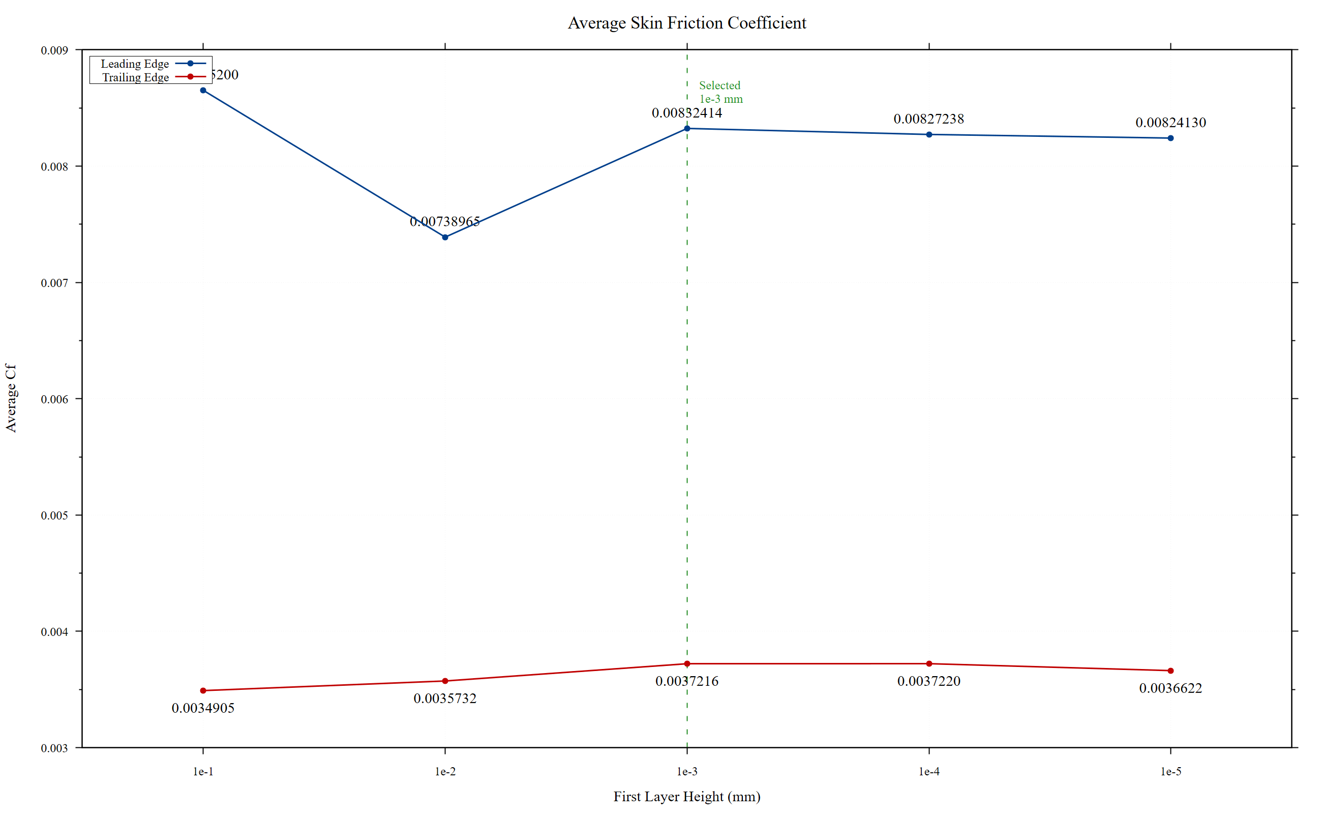
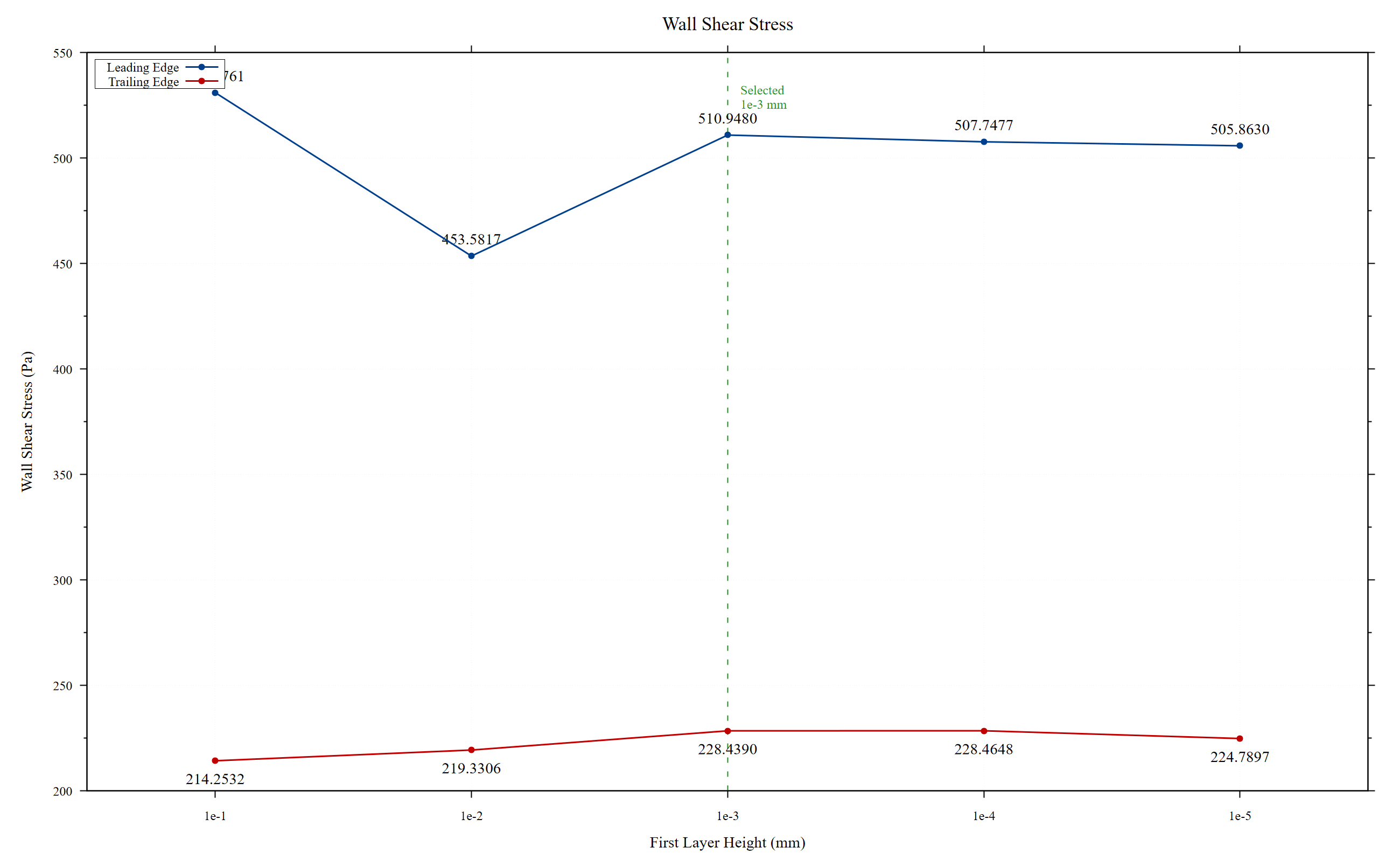
Both metrics are essentially unchanged from 1e-3 mm through 1e-5 mm, which is why 1e-3 mm was picked as the production first-layer height — on the flat part of the curve, not still changing with further refinement.
Sample result
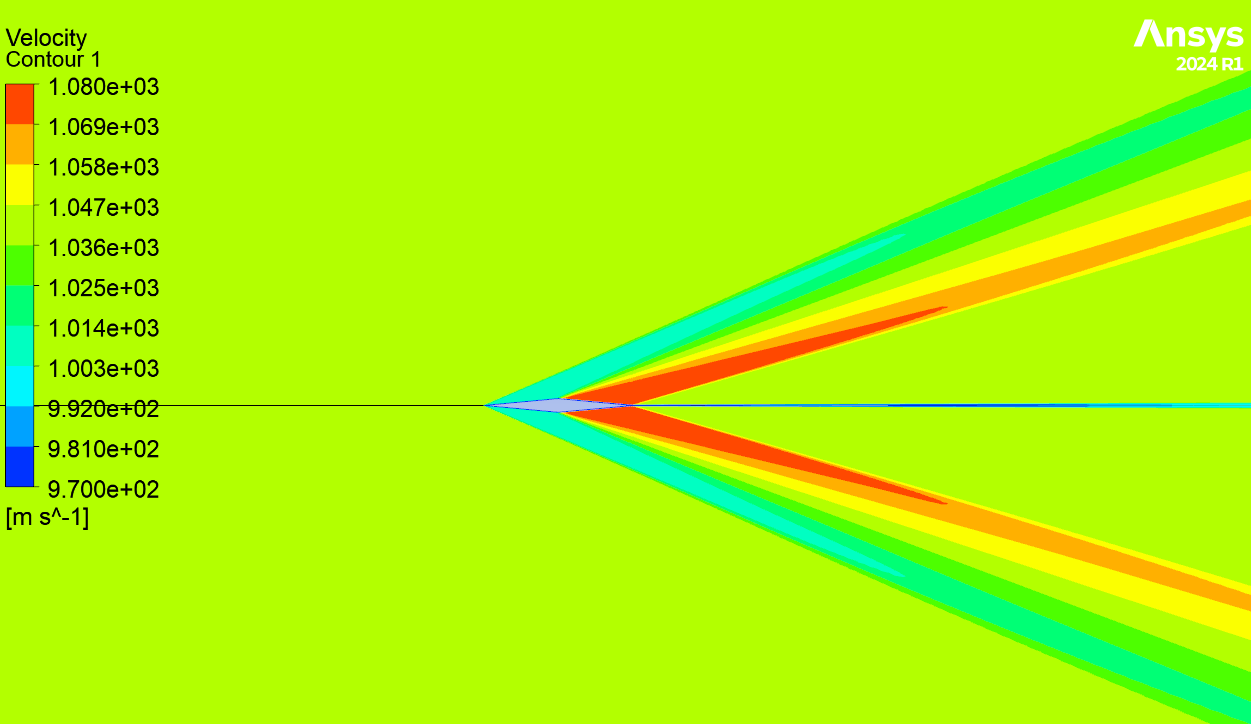
Comparison
Two checks, in order: smooth-wall CFD against the analytical prediction (validates the solver against theory), then rough-wall CFD against smooth-wall CFD (the actual research question) — shock angle, Cf, wall shear stress, and near-wall y⁺.
This report's own conclusions chapter is written as a template pending final numbers ("final conclusions will be updated after completion of the simulation matrix"), even though the results chapter already has the mesh-independence data above plus smooth-wall contours. Treat this as a mid-revision academic report: the raw CFD case files aren't included in the repo, only the PDF and its figures — nothing here is runnable, and roughness results are only as good as the sand-grain wall function's validity range for the given ks/boundary-layer-thickness ratio.
Remaining work per the report: final double-wedge geometry/freestream numbers, additional roughness heights and higher Mach numbers, and 3D / realistic random-roughness simulations.